Device for increasing the exhaust velocity of a pneumatic regulating valve

A technology of exhaust speed and regulating valve, which is applied in the direction of valve operation/release device, valve device, control valve and air release valve, etc., which can solve the problems of reducing exhaust speed, unfavorable exhaust air flow, and abnormal exhaust air flow. Best etc.

Active Publication Date: 2021-03-26
ZF CV SYST EURO BV
View PDF8 Cites 0 Cited by
  • Summary
  • Abstract
  • Description
  • Claims
  • Application Information

AI Technical Summary

Problems solved by technology

The channel cross-section of the exhaust connection is thus narrowed and a non-optimal conduction of the exhaust air flow results due to the rupture of the area between the annular sealing seat on the cylindrical projection and the tubular extension. Air flow detrimentally reduces exhaust velocity

Method used


Image

  • Device for increasing the exhaust velocity of a pneumatic regulating valve
  • Device for increasing the exhaust velocity of a pneumatic regulating valve
  • Device for increasing the exhaust velocity of a pneumatic regulating valve

Examples


Embodiment Construction

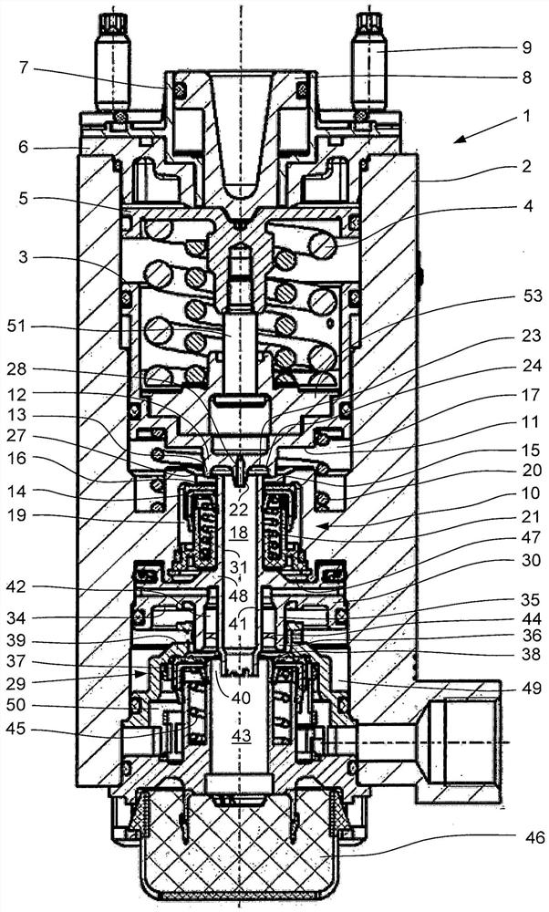
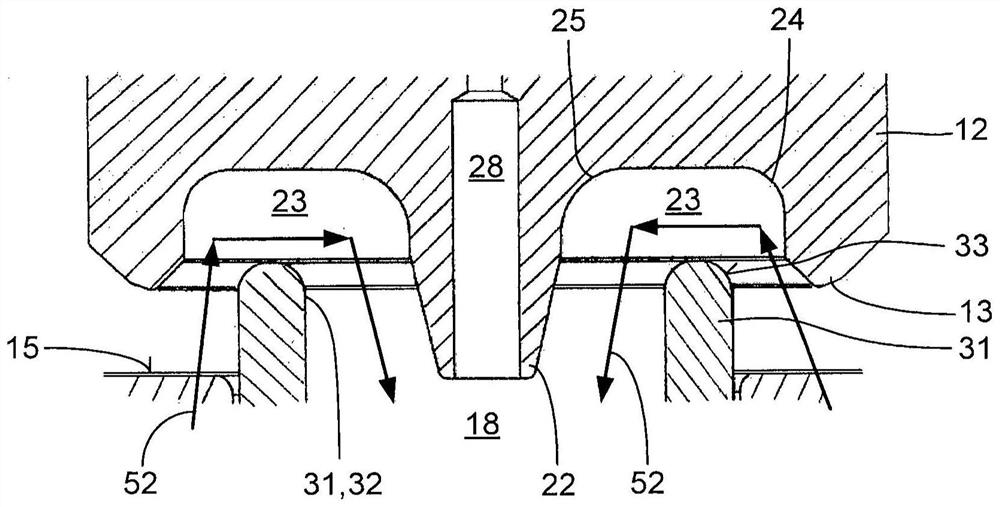
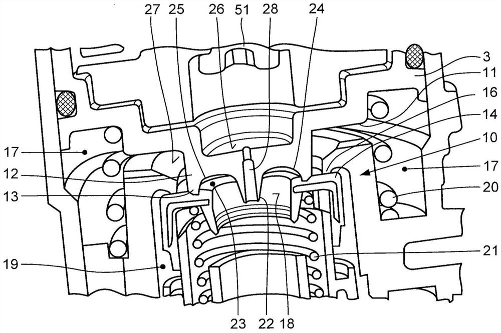
[0018] A regulating valve 1 designed as a brake value indicator for a dual-circuit brake system of a motor vehicle has a housing 2 in which a first valve piston 3 is guided in a sealing manner. The plunger 8 is axially guided on the housing cover 6 in a hollow-cylindrical guide 7 . The housing cover 6 together with the guide 7 is screwed onto the housing 2 by means of fastening screws 9 . Arranged below the underside 11 of the first valve piston 3 is a first valve system 10 comprising a cylindrical projection 12 and an annular sealing seat 13 arranged on the free end of the projection. The first valve piston 3 of the first valve piston 3, the annular first plate valve 14 with the radial sealing surface 15, and the annular sealing seat 13 having a diameter larger than that on the cylindrical protrusion 12 of the first valve piston 3 A large, immovable annular first seal seat 16.

[0019] The cylindrical protrusion 12 on the first valve piston 3 and the immovable, annular firs...


PUM


Abstract

The invention relates to a device for adjusting the brake pressure in a control valve designed as a brake value indicator corresponding to a desired braking effect in a single-circuit or double-circuit compressed air brake system for a vehicle , wherein the regulating valve (1) has at least one pneumatic first valve system (10). In order to increase the exhaust velocity, at least in the area of ​​the exhaust duct (18) of the at least one pneumatic first valve system (10) there is a rounded transition for guiding the exhaust air flow (52) in a flow-favorable manner Ministry (24, 25).

Description

technical field [0001] The invention relates to a device for increasing the discharge rate of a pneumatic regulating valve having at least one first valve system with an axially displaceable first valve piston, the first valve On its underside, the piston has an axially protruding, annular sealing seat arranged on the end of the cylindrical projection, which is in contact with a radial seal on the axially displaceable annular first plate valve. The sealing surface of the first plate valve cooperates, wherein the radial sealing surface of the first plate valve also cooperates with a coaxial, annular and non-movable first sealing seat whose diameter is larger than that of the sealing seat on the first valve piston , wherein the sealing seat on the first valve piston is lifted from the radial sealing surface of the first plate valve in the rest position of the first valve piston and the radial sealing surface of the first plate valve rests against On the immovable first sealing ...

Claims


Application Information

Patent Timeline
Patent Type & Authority Patents(China)
IPC IPC(8): B60T15/04B60T15/18F16K1/06
CPCB60T15/046B60T15/18F16K31/1221F16K1/52F16K1/526
Inventor 彼得·拜尔维尔纳·德赖尔彼得拉·埃尔策亚历山大·法比安斯文·霍曼扬·霍斯特曼贝蒂纳·马滕斯格哈德·马丁尼卡尔-海因茨·里迪格-雅尼施
Owner ZF CV SYST EURO BV
Why Eureka
Try Eureka