
optical routing equipment

A device and optical path technology, applied in the field of optical routing equipment, which can solve the problems of optical switch limitation, lack of flexibility, and inability to support flexible grids.

Active Publication Date: 2020-04-03
HUAWEI TECH CO LTD
View PDF4 Cites 0 Cited by
  • Summary
  • Abstract
  • Description
  • Claims
  • Application Information

AI Technical Summary

Problems solved by technology

[0004] However, since AWG devices can only support fixed-wavelength channels and cannot support flexible-grid networks, the use of the above-mentioned optical switches that use AWG to implement space-wavelength routing is limited and lacks flexibility.

Method used


Image

  • optical routing equipment
  • optical routing equipment
  • optical routing equipment

Examples


Embodiment Construction

[0033] In order to make the purpose, technical solutions and advantages of the embodiments of the present invention clearer, the technical solutions in the embodiments of the present invention will be clearly and completely described below in conjunction with the drawings in the embodiments of the present invention. Obviously, the described embodiments It is a part of embodiments of the present invention, but not all embodiments. Based on the embodiments of the present invention, all other embodiments obtained by persons of ordinary skill in the art without creative efforts fall within the protection scope of the present invention.

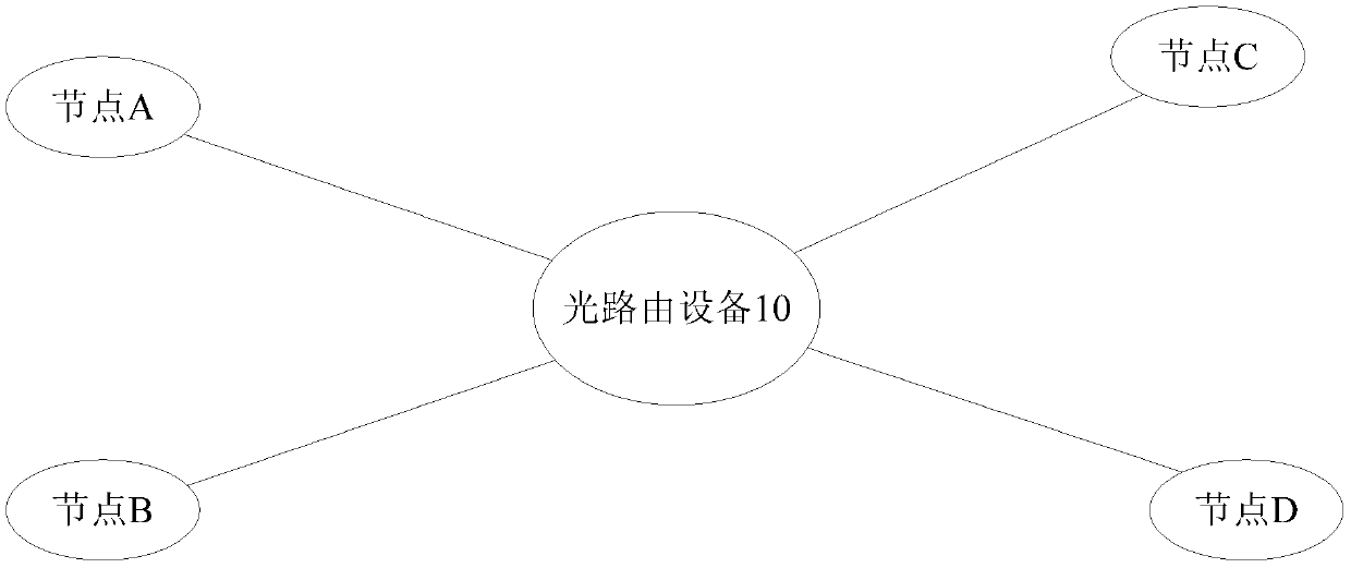
[0034] figure 1 It is a schematic diagram of the application scene of the optical routing device of the present invention, such as figure 1As shown, the optical routing device of this embodiment can be specifically applied in the optical interconnection scenario, specifically, it can realize the interconnection between one or more nodes and one o...


PUM


Abstract

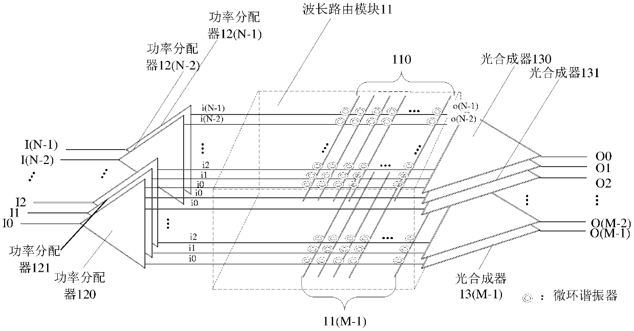
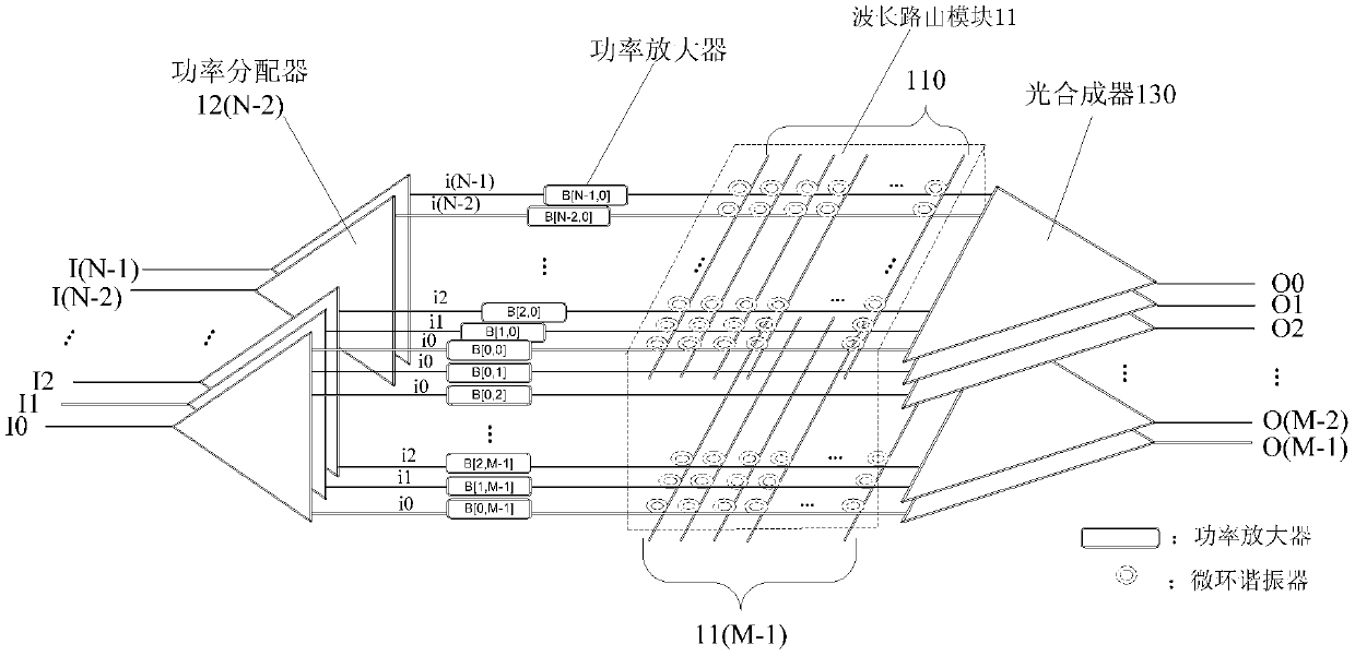
An optical routing device, comprising: N first input terminals (I0, I1, ..., I(N-1)), M first output terminals (O0, O1, ..., O(M-1)) and a wavelength routing module (11). The wavelength routing module (11) comprises M micro-ring arrays (110, 111, ..., 11(M-1)), and each micro-ring array (110, 111, ..., 11(M-1)) comprises N second input terminals (i0, i1, ..., i(N-1) and N second output terminals (o0, o1, ..., o(N-1)); each second input terminal (i0, i1, ..., i(N-1)) of each micro-ring array (110, 111, ..., 11(M-1)) is used for receiving an optical signal input by a corresponding first input end terminal (I0, I1, ..., I(N-1)); and the N second output terminals (o0, o1, ..., o(N-1)) of each micro-ring array (110, 111, ..., 11(M-1)) are used for connecting a corresponding first output terminal (O0, O1, ..., O(M-1)). The optical routing device may support a transmission channel of any wavelength without altering hardware structure, thereby making use of the device more flexible.

Description

technical field [0001] Embodiments of the present invention relate to optical communication technology, and in particular to an optical routing device. Background technique [0002] With the popularity of applications such as interactive network television (abbreviated as IPTV) and cloud storage, Internet traffic continues to grow, and higher requirements are placed on the capacity and energy consumption of switch nodes in core networks and data centers. The bandwidth upgrade of existing electric domain switches is limited in terms of technology and energy consumption, while future interconnection technologies require high connectivity, high capacity, low latency, low power consumption, and low cost. Therefore, optical switches are regarded as important enabling devices for next-generation switching systems. [0003] At present, the integrated optical switch mainly realizes the spatial routing function. However, with the popularity of Wavelength Division Multiplexing (WDM)...

Claims


Application Information

Patent Timeline
Patent Type & Authority Patents(China)
IPC IPC(8): H04Q11/00G02B6/293
CPCG02B6/293H04Q11/00
Inventor 程祺翔
Owner HUAWEI TECH CO LTD
Learn More