Card stacking and putting mechanism

A technology of card and material blocking mechanism, which is applied in the direction of sending objects, stacking receiving devices, and thin material processing, etc. It can solve the problems of low efficiency of manual card codes, and achieve the effect of improving production efficiency and simple device structure

Pending Publication Date: 2018-06-12
BEAUTIFUL CARD TECH SUZHOU CO LTD
0 Cites 0 Cited by

AI-Extracted Technical Summary

Problems solved by technology

[0003] The technical problem to be solved by the present invention is to provide a c...

Abstract

The invention discloses a card stacking and putting mechanism which comprises a square material barrel, elastic sheets, air cylinders, connecting plates, temporary storage sleeves, material blocking mechanisms, electromagnets and silica gel sleeves; cards are put in the square material barrel and are automatically centered by the four symmetrically arranged elastic sheets; subsequently, the cardsfall into the temporary storage sleeves under the action of gravity; the two symmetrically arranged material blocking mechanisms block the cards so as to prevent the cards from continuing to fall; subsequently, the two symmetrically arranged air cylinders push the temporary storage sleeves fixedly connected with the connecting plates to move downwards till the silica gel sleeves are bonded with the externally arranged card putting mechanism; subsequently, the electromagnets are electrified so as to attract attraction iron to drive square material blocking rods to move outwards; subsequently, the cards freely fall to the middle of the externally arranged card putting mechanism; and when discharging is completed, the electromagnets are electrified, and springs drive the square material blocking rods to be reset. The card stacking and putting mechanism is simple in structure, and the cards can be conveyed to the externally arranged card putting mechanism automatically and orderly, so thatmanual operation is replaced, and the production efficiency is improved.

Application Domain

Pile receiversArticle delivery

Technology Topic

ElectricityEngineering +5

Image

  • Card stacking and putting mechanism
  • Card stacking and putting mechanism

Examples

  • Experimental program(1)

Example Embodiment

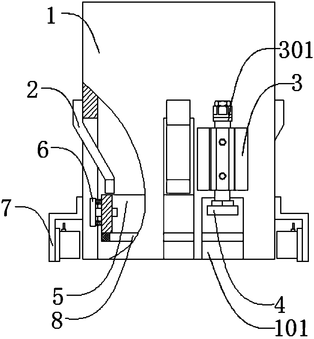
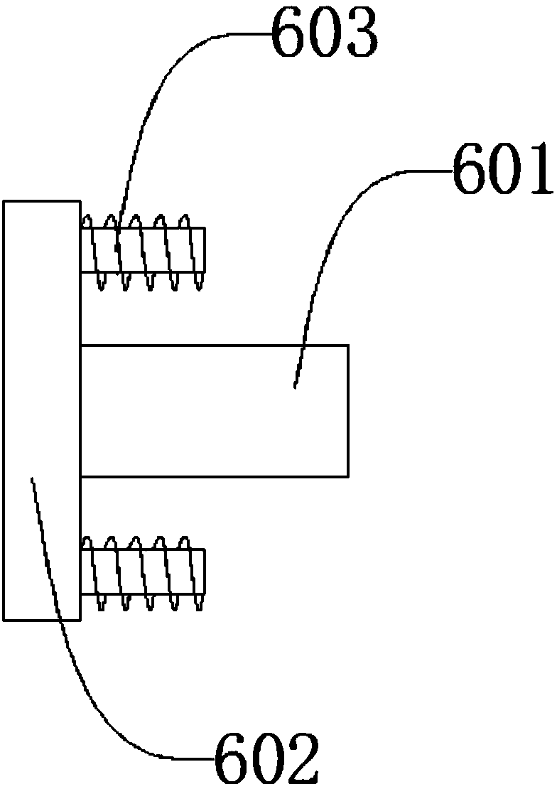
[0016] Such as figure 1 , figure 2 As shown, a card stacking mechanism includes a square barrel 1, elastic pieces 2, cylinder 3, connecting plate 4, buffer sleeve 5, stopper mechanism 6, electromagnet 7, and silicone sleeve 8. The number of elastic pieces 2 is 4 The cylinder 3 is located on the outside of the square cylinder 1, the cylinder 3 is connected to the square cylinder 1 by bolts, and the connecting plate 4 is located on the cylinder 3. The lower end penetrates through the square barrel 1, the connecting plate 4 is connected with the cylinder 3 by bolts, the buffer sleeve 5 is located on the side of the connecting plate 4 and inside the square barrel 1, the buffer sleeve 5 and the connecting plate 4 is connected by welding, the buffer sleeve 5 is also provided with a blocking mechanism 6, the electromagnet 7 is located at the lower end of the outer side of the rectangular barrel 1, and the electromagnet 7 is connected with the rectangular barrel 1 by bolts. The silicone sleeve 8 is located at the lower end of the buffer sleeve 5. The silicone sleeve 8 is bonded and connected to the buffer sleeve 5. The number of cylinders 3 is two, and they are arranged symmetrically along the square barrel 1. The stopper mechanism 6 The quantity is 2 pieces, which are arranged symmetrically along the buffer sleeve 5, and the electromagnet 7 is 2 pieces in quantity, which are arranged symmetrically along the square barrel 1. The square barrel 1 is also provided with an escape groove 101. The avoidance groove 101 penetrates through the main body of the rectangular barrel 1, the cylinder 3 is further provided with an adjusting nut 301, the adjusting nut 301 is located at the upper end of the cylinder 3, and the adjusting nut 301 is threadedly connected to the cylinder 3, The stopper mechanism 6 also includes a square stopper rod 601, a suction iron 602, and a spring 603. The square stopper rod 601 penetrates the buffer sleeve 5, and the square stopper rod 601 can run along the buffer sleeve 5. Sliding, the pull-in iron 602 is located outside the square stop bar 601, the pull-in iron 602 and the square stop bar 601 are connected by bolts, and the spring 603 is located between the pull-in iron 602 and the buffer sleeve 5. The springs 603 are respectively welded and connected with the suction iron 602 and the buffer sleeve 5. The card stacking mechanism puts the card in the square barrel 1 when it works, and the four symmetrically arranged shrapnel 2 automatically center the card. Subsequently, the card falls into the buffer sleeve 5 by gravity, and two symmetrically arranged stopper mechanisms 6 block the card to prevent the card from falling further. Then, two symmetrically arranged cylinders 3 push the buffer sleeve fixedly connected to the connecting plate 4 5 Move down until the silicone sleeve 8 is attached to the external card placement mechanism. At this time, the axis of the electromagnet 7 coincides with the axis of the square stopper rod 601, and then the electromagnet 7 is energized to attract the attracting iron 602 Close, thereby driving the square stop bar 601 to move outward, and then, the card falls freely in the external card placement mechanism. When the feeding is finished, the electromagnet 7 is energized, and the spring 603 drives the square stop bar 601 to reset. The device has a simple structure and can automatically send the cards neatly to the card placement mechanism of the peripheral device, thereby replacing manual manual operation and improving production efficiency.
[0017] The present invention is not limited to the above-mentioned specific implementations. Starting from the above-mentioned concept and without creative work, various changes made by those skilled in the art fall within the protection scope of the present invention.

PUM

no PUM

Description & Claims & Application Information

We can also present the details of the Description, Claims and Application information to help users get a comprehensive understanding of the technical details of the patent, such as background art, summary of invention, brief description of drawings, description of embodiments, and other original content. On the other hand, users can also determine the specific scope of protection of the technology through the list of claims; as well as understand the changes in the life cycle of the technology with the presentation of the patent timeline. Login to view more.

Similar technology patents

Device and method for generating terahertz wave based on nested Mach-Zehnder modulator

InactiveCN102854695AReduce bandwidth requirementsSimple device structure
Owner:HUNAN UNIV OF TECH

Classification and recommendation of technical efficacy words

  • Increase productivity
  • Simple device structure

Preparation method of super-retarding type polycarboxylate superplasticizer

ActiveCN103848944AIncrease productivityUniform product
Owner:KZJ NEW MATERIALS GROUP CO LTD
Why Eureka
Try Eureka