
Hydraulic impactor regulated and controlled by piston

A technology of hydraulic impactor and piston, which is applied in the direction of drilling driving device, drilling equipment, earthwork drilling and production in the wellbore, which can solve the problems of poor impact effect of hydraulic impactor and achieve the effect of increasing drilling speed

Active Publication Date: 2018-06-12
NORTHEAST GASOLINEEUM UNIV
View PDF4 Cites 0 Cited by
  • Summary
  • Abstract
  • Description
  • Claims
  • Application Information

AI Technical Summary

Problems solved by technology

[0003] An object of the present invention is to provide a hydraulic impactor regulated by a piston, which is used to solve the problem of poor impact effect of existing hydraulic impactors

Method used


Image

  • Hydraulic impactor regulated and controlled by piston
  • Hydraulic impactor regulated and controlled by piston
  • Hydraulic impactor regulated and controlled by piston

Examples


Embodiment Construction

[0019] Below in conjunction with accompanying drawing, the present invention will be further described:

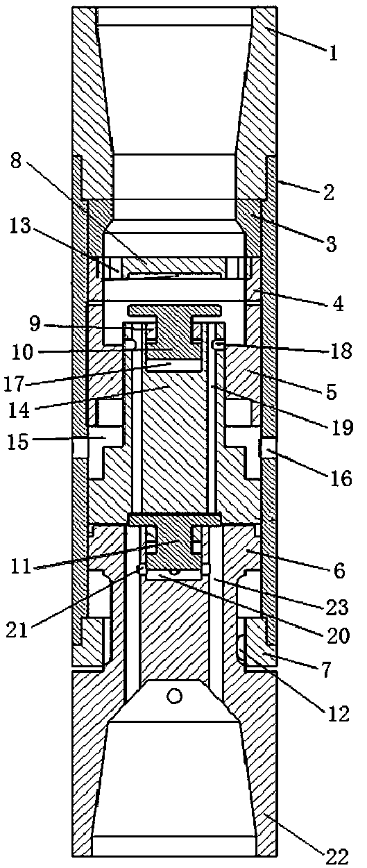
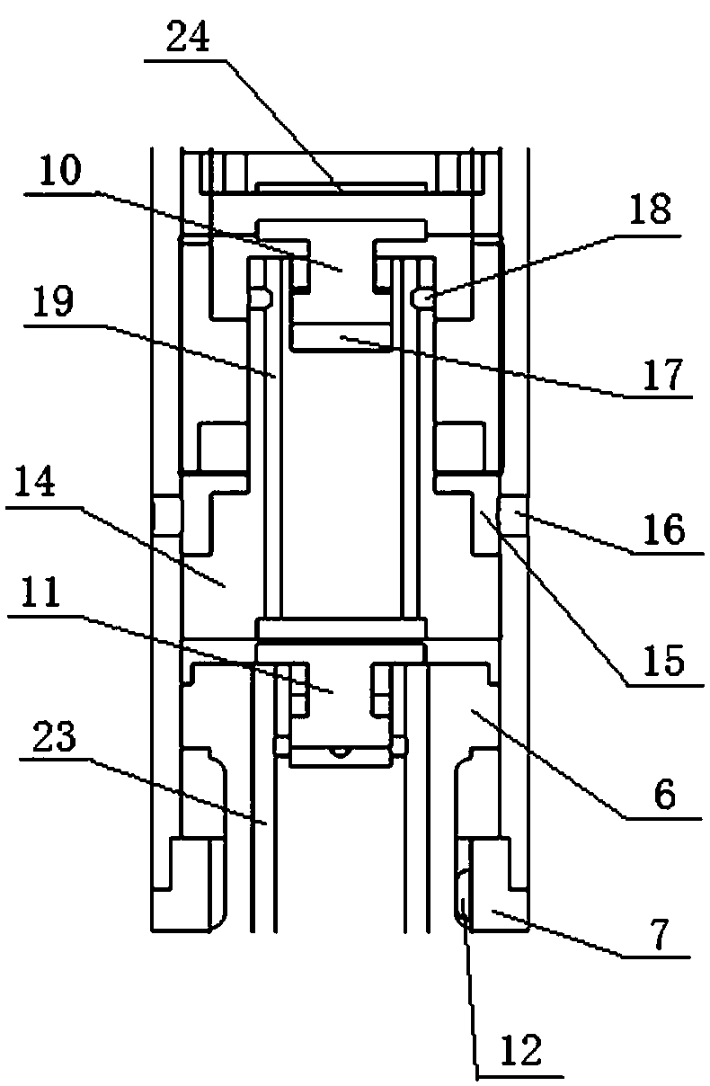
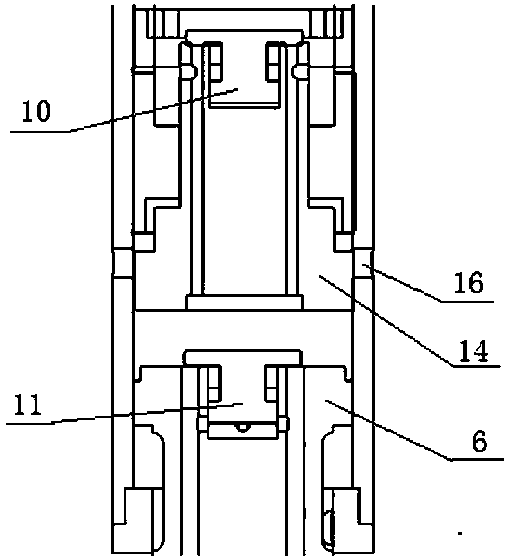
[0020] Such as figure 1 As shown, the piston-controlled hydraulic impactor includes an upper conversion joint 1, an upper spacer sleeve 3, a housing 2, a valve cover 8, an impact hammer 14, an anvil 6, and a limit nut 7. The upper conversion joint 1 passes through The thread is connected with the drill collar, and the lower adapter 22 is connected with the drill bit through the thread; the shell 2 is a cylinder, the upper end of the shell 2 is threaded with the upper adapter 1, the anvil 6 is set at the lower end of the shell 2, and the limit nut 7 is set Between housing 2 and anvil 6, stop nut 7 and anvil 6 are provided with drive pin 12, and the lower end of anvil 6 is lower conversion joint 22, and stop nut 7 is used for limiting the movement of anvil 6; 5 is fastened in the housing 2, the upper spacer sleeve 3 and the valve seat 4 are arranged between the upper conver...


PUM


Abstract

The invention relates to a hydraulic impactor regulated and controlled by a piston. The upper end of a shell of the hydraulic impactor regulated and controlled by the piston is connected with an upperportion switching joint in a threaded mode; the lower end of the shell is provided with an anvil; the lower end of the anvil is provided with a lower portion switching joint; a cylinder body is fastened in the shell; an upper portion spacing sleeve and an upper valve seat are arranged between the upper portion switching joint and the cylinder body; a valve cover is arranged in the upper valve seat; a passageway is arranged around the valve cover; a valve cavity is formed by the valve cover and the cylinder body; an impact hammer passes through the cylinder body and stretched into the valve cavity; the bottom of the impact hammer contacts with the shell; a low pressure cavity is formed between the impact hammer and the cylinder body; the shell is provided with a low voltage channel, and the a low pressure chamber communicates with a annulus by the low voltage channel; the upper end of the anvil is provided with a valve cylinder; a first piston bottom plate is located in the valve cylinder; the upper end of the anvil is provided with a valve barrel, and the second piston bottom plate is located in the valve barrel; the second piston bottom plate is a free end; the bottom of the impact hammer is provided with a piston groove; and when the piston is connected with the anvil, and a second piston top plate is located in the piston groove. The hydraulic impactor controlled by the piston solves the problem of a poor impact effect of an existing hydraulic impactor.

Description

technical field [0001] The invention is applied to the fields of petroleum engineering, mining engineering, geotechnical engineering, etc., and is a hammer that uses fluid to generate power. It is used in combination with rotary drilling equipment to exert impact on a drill bit, and specifically relates to a hydraulic hammer regulated by a piston. Background technique [0002] With the rapid development of my country's national economy, the country's demand for oil and gas resources is increasing year by year. The intensity of oil and gas exploration continues to increase, and the difficulty of mining is increasing. The mining layer changes from shallow layer to deep layer and ultra-deep layer. The drilling speed is severely restricted, so it is urgent to increase the drilling speed. At present, impactors are used to impact the drill bit to increase the drilling speed, which is widely used in the drilling process. During rotary percussion drilling, it has been achieved th...

Claims


Application Information

Patent Timeline
Patent Type & Authority Applications(China)
IPC IPC(8): E21B4/16
CPCE21B4/16
Inventor 李玮闫铁吴红军赵欢李世昌李建冰
Owner NORTHEAST GASOLINEEUM UNIV
Learn More