Oscillation impact testing device

A shock test and launcher technology, applied in shock test, measuring device, ammunition test, etc., can solve the problems of insufficient test accuracy, limited test result authenticity, unstable control of test conditions, etc., to achieve convenient installation and disassembly, Realize the effect of fast impact and strong work ability

Inactive Publication Date: 2015-05-13
XIAN MODERN CHEM RES INST
View PDF3 Cites 0 Cited by
  • Summary
  • Abstract
  • Description
  • Claims
  • Application Information

AI Technical Summary

Problems solved by technology

In the impact pendulum test, the propellant sample needs to be made into a single-hole tubular charge of a certain size, which is different from the actual propellant charge sample and cannot reflect the real strength of the propellant sample; the drop weight test and the Hopkins rod test require Grinding the end face of the propellant, the processing status has a great influence on the strength test of the propellant, the test accuracy is insufficient, and the test for a single propellant cannot reflect the state of mutual impact and extrusion when the charge bed hits; the semi-closed detonator The test did not involve the impact process of the propellant bed; the gas cannon impact test, which simulates the impact and extrusion of the propellant bed, simulates the impact and extrusion state of the propellant in the process of weapon firing to a certain extent, but the control of the test conditions is not sufficient. Stable, and it is impossible to simulate the multiple impact and extrusion process of propellant in the weapon chamber
[0006] To sum up, all the existing test methods are different from the actual impact state of the propellant bed, the force state cannot truly reflect the actual state, and the authenticity of the test results is limited

Method used


Image

  • Oscillation impact testing device
  • Oscillation impact testing device
  • Oscillation impact testing device

Examples


Embodiment Construction

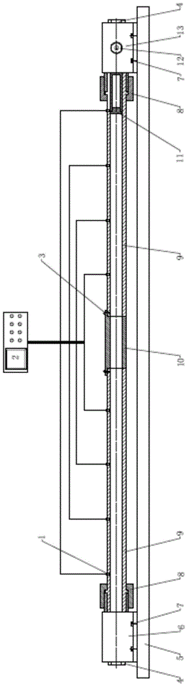
[0034] like figure 1 , Figure 4 and Figure 5 As shown, the shock and impact test device of the present embodiment includes an oscilloscope 2, a sensor 1, a stand 5, a body tube seat 6, two body tube connecting hoops 8, two body tubes 9, a guide tube 10, a carrier 11, Launcher 12 and launcher seat 13. in:

[0035] The stand 5 is a cuboid, made of square steel, with 8 holes on both sides for installing the barrel seat 6 and the launcher seat 13.

[0036] The body tube seat 6 is a cylinder with two ends open, and its inner hole is a circular stepped hole, and the end of the smaller section of the body tube seat 6 is provided with an external thread cylindrical boss, and the screw on the boss Connect with a plug 4 to close this end of the barrel seat 6; the seat plug 4 is a circular cover with an internal thread matched with the external thread of the boss.

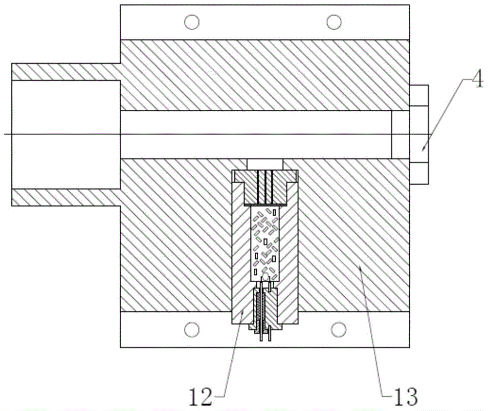
[0037] The launcher seat 13 is a cylinder with two ends open, and its inner hole is a circular stepped hole, and the s...


PUM


Abstract

The invention discloses an oscillation impact testing device. The oscillation impact testing device comprises a sensor, an oscilloscope, a frame foundation, a barrel seat, two barrel connecting hoops, two barrels, a guide tube, a vehicle, a launcher and a launcher seat. The frame foundation is fixed onto a test stand, the barrel seat and the launcher seat are fixed to the two ends of the frame foundation respectively and are coaxial. The two barrels are coaxially connected with the barrel seat and the launcher seat through the barrel connecting hoops. The other ends of the two barrels are fixed to the inner portion of the guide tube. The vehicle is installed inside the barrel connected with the launcher seat. A plurality of pressure sensors are evenly arranged on the lateral walls of the two barrels in the axial direction. The pressure sensors are connected with the oscilloscope. The launcher is installed inside the launcher seat. By means of the oscillation impact testing device, the oscillation impact state inside a propellant bed bore can be better simulated, the mechanical property in the propellant powder action process can be evaluated objectively and truly, the basic performance of different propellant powder dynamic mechanical strengths is obtained by comparing the broken state of powder particles before collision and the broken state of the powder particles after collision and a technological means is provided for studying high-strength propellant powder and improving the technical level of high-gun-pressure guns.

Description

technical field [0001] The invention belongs to the technical field of explosives, and in particular relates to a shock and impact test device. Background technique [0002] With the continuous improvement of the performance of guns and weapons, higher requirements have been put forward for the propellant of projectile launching energy. Adaptability, the low vulnerability of weapons needs to be improved. To achieve the above goals, countries generally adopt the method of adding high-energy solid components to increase the energy level of the propellant, or adding low-sensitivity solid explosives to improve the low vulnerability of the propellant. The basic medicine is the main one. [0003] While improving the performance of the propellant, it also brings new problems, which are prominently manifested as the reduction of the strength of the propellant, which greatly reduces the safety of the artillery launch. Explosion accidents occur from time to time, seriously hinderin...

Claims


Application Information

Patent Timeline
Patent Type & Authority Patents(China)
IPC IPC(8): F42B35/00G01M7/08
Inventor 陈晓明杨丽侠张衡赵宏立刘来东靳建伟赵宝明张邹邹
Owner XIAN MODERN CHEM RES INST
Why Eureka
Try Eureka