Unlock instant, AI-driven research and patent intelligence for your innovation.

Automatic shaft locking mechanism

A shaft locking, automatic technology, applied in the direction of brake actuators, gear transmission mechanisms, mechanical equipment, etc., can solve the problems of shortening the service life of the shaft, troublesome operation, etc., and achieve the effect of fast fixing speed, convenient operation and simple structure

Inactive Publication Date: 2018-06-12
CHONGQING LONGJIAN METAL MFG
View PDF0 Cites 0 Cited by
  • Summary
  • Abstract
  • Description
  • Claims
  • Application Information

AI Technical Summary

Problems solved by technology

The rotating shaft is basically used to adjust the rotation of the shaft within a certain period of time. When it is rotated at a certain angle, it needs to be fixed. At present, the commonly used method of fixing is a snap-in fixing method, which is very cumbersome to operate and takes a long time. Repeated fastening will shorten the service life of the shaft

Method used


Image

  • Automatic shaft locking mechanism

Examples


Embodiment

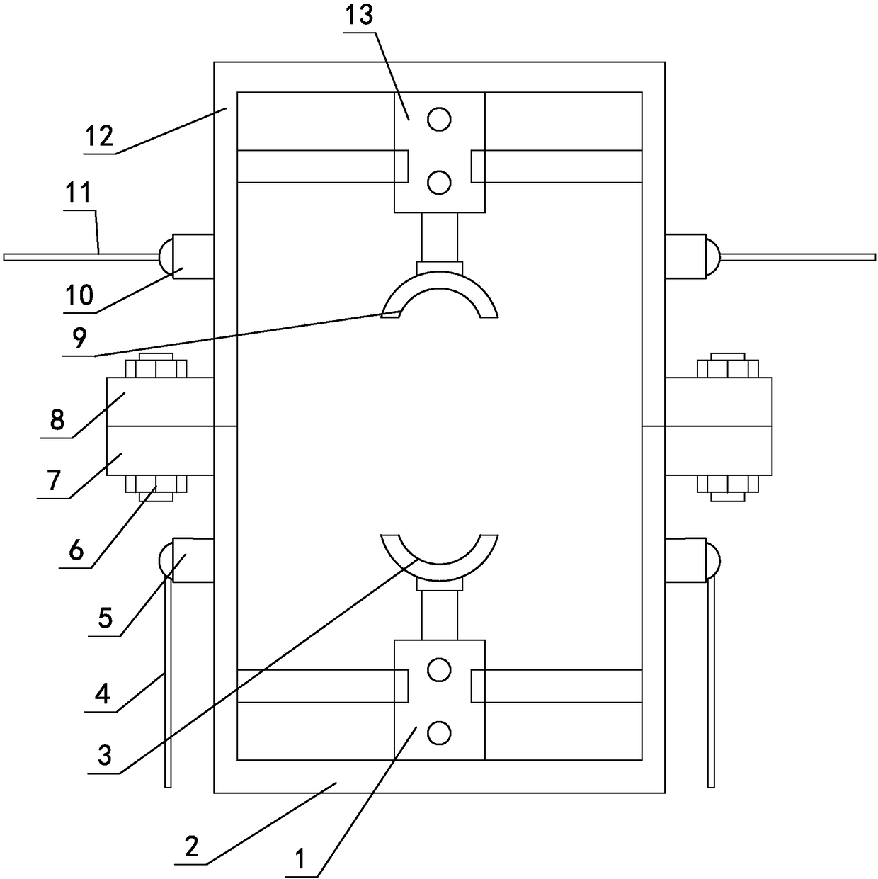
[0014] Such as figure 1 As shown, the automatic shaft locking mechanism includes a lower mounting frame 2 and an upper mounting frame 12 that cooperate up and down. The lower mounting frame 2 and the lower mounting frame 2 constitute a frame structure, and the left and right sides of the lower mounting frame 2 are provided with The lower connecting seat 7 is provided with an upper connecting seat 8 cooperating with the lower connecting seat 7 on the left and right sides of the upper mounting frame 12, and the lower connecting seat 7 is connected with the upper connecting seat 8 through a bolt 6, and the upper and lower connecting seats are arranged in the frame structure. The upper clamping block 9 and the lower clamping block 3 matched by the pair of clips, the top of the upper clamping block 9 is vertically provided with an upper hydraulic cylinder 13, and the cylinder body of the upper hydraulic cylinder 13 is installed on the upper mounting frame 12, and its piston rod and ...


PUM


Abstract

The invention relates to an automatic shaft locking mechanism, and belongs to the technical field of shaft locking. The automatic shaft locking mechanism comprises a lower installation frame and an upper installation frame which are matched in the up-down direction, wherein the lower installation frame and the upper installation frame form a frame-shaped structure; lower connection seats are arranged at the left side and the right side of the lower installation frame; upper connection seats in matching connection with the lower connection seats are arranged at the left side and the right sideof the upper installation frame; the lower connection seats are connected with the upper connection seats through bolts; an upper clamping block and a lower clamping block which are oppositely clampedand matched in the up-down direction are arranged in the frame-shaped structure; an upper hydraulic cylinder is vertically arranged above the upper clamping block, the cylinder body of the upper hydraulic cylinder is installed on the upper installation frame, and the piston rod of the upper hydraulic cylinder is connected with the upper clamping block; and a lower hydraulic cylinder is verticallyarranged below the lower clamping block, the cylinder body of the lower hydraulic cylinder is installed on the lower installation frame, and the piston rod of the lower hydraulic cylinder is connected with the lower clamping block. The automatic shaft locking mechanism adopting the design is quite convenient to operate, time-saving and labor-saving, and high in fixing speed during fixing for a rotary shaft.

Description

technical field [0001] The invention relates to an automatic shaft locking mechanism, which belongs to the technical field of shaft locking. Background technique [0002] Shafts are one of the most common workpieces in the mechanical field. There are transmission shafts for power transmission, rotating shafts for rotation, and fixed shafts for fixed installation. The rotating shaft is basically used to adjust the rotation of the shaft within a certain period of time. When it rotates at a certain angle, it needs to be fixed. At present, the commonly used method of fixing is the snap-in fixing method, which is very troublesome to operate and takes a long time. Repeated fastening will shorten the service life of the shaft. Contents of the invention [0003] According to the deficiencies in the prior art above, the technical problem to be solved by the present invention is: to provide an automatic shaft locking mechanism, which has a simple structure and is very convenient to...

Claims


Application Information

Patent Timeline
IPC IPC(8): F16D65/14F16H57/00F16D121/04
CPCF16D65/14F16D2121/04F16H57/00
Inventor 秦秉宏
Owner CHONGQING LONGJIAN METAL MFG