Calculation method for steel rail potential current distribution influences

A technology of current distribution and calculation method, applied in calculation, power track, complex mathematical operation, etc., can solve problems such as excessive rail potential and rail current, and achieve the effect of ensuring safe and reliable operation

Inactive Publication Date: 2018-06-12
SOUTHWEST JIAOTONG UNIV
View PDF4 Cites 8 Cited by
  • Summary
  • Abstract
  • Description
  • Claims
  • Application Information

AI Technical Summary

Problems solved by technology

Compared with when there is only one EMU running in a power supply arm, multi-car operation is more likely to cause excessively high rail potential and rail current, and is affected by the distance between multiple cars

Method used


Image

  • Calculation method for steel rail potential current distribution influences
  • Calculation method for steel rail potential current distribution influences
  • Calculation method for steel rail potential current distribution influences

Examples


Embodiment Construction

[0030] The present invention will be further described in detail below in conjunction with the drawings and specific embodiments.

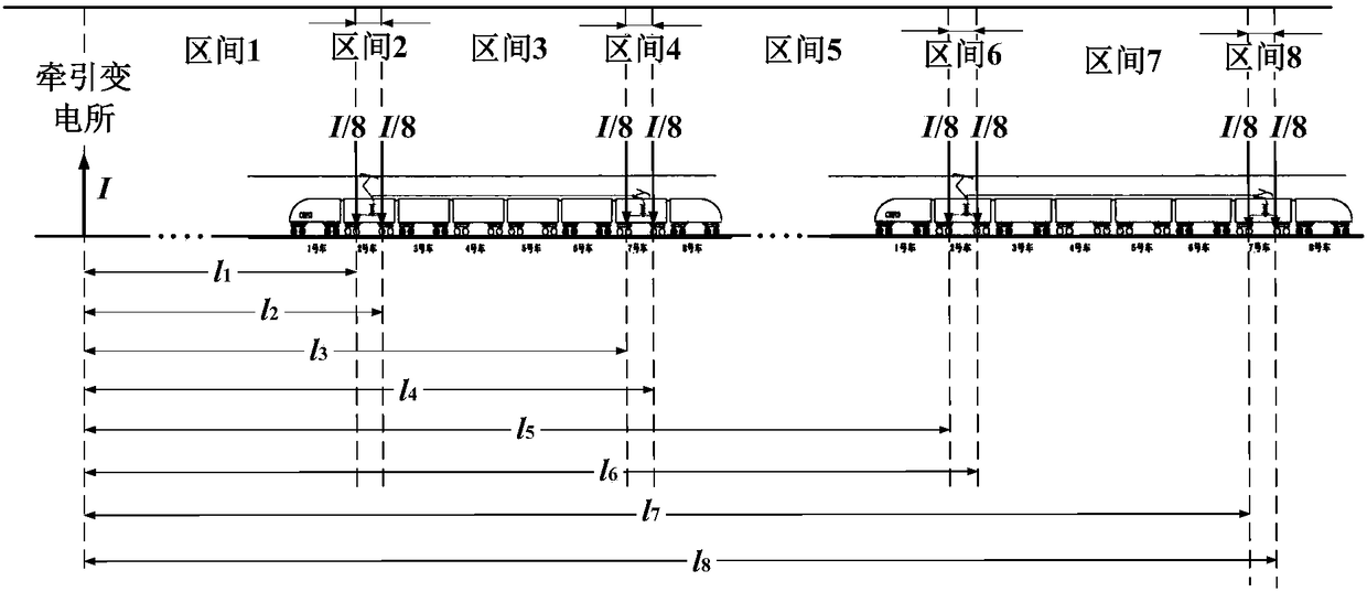
[0031] Taking the case where two CRH3 EMUs are operated in the same power supply arm as an example, the present invention will be further elaborated, including the following steps:

[0032] Step 1: Considering that the CRH3 EMU has 4 working grounding points, it is determined that the traction current in the power supply arm is injected into the rail-earth circuit in 8 parts, and is aggregated and flowed out at the traction substation; the feedback is fed back to the traction substation The total backflow current is decomposed into 8 parts, and the road section between the traction substation and the working grounding point farthest from the traction substation is divided into 8 different sections according to the injection position of each sub-return current on the rail.

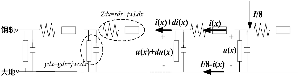
[0033] Step 2: Consider only a single sub-return current exists in the pow...


PUM

PropertyMeasurementUnit
depthaaaaaaaaaa

Abstract

The invention discloses a calculation method for steel rail potential current distribution influences. The method comprises the steps that on the basis of the injection rate of each return current ona steel rail, the return current collected at a traction substation is resolved, and according to the injection position of each sub-return current on the steel rail, a power supply arm road section is divided into different sections; according to each sub-return current injected on the steel rail, by writing a steel rail potential and steel rail current differential equation, excitation source response and sensibility interference incident field excitation response steel rail potential and steel rail current calculation formulas are adopted when each sub-return current is injected into (flowsout of) a steel rail-ground return, and then according to the boundary conditions, steel rail potential and current distribution is obtained; finally, the steel rail potential and current caused by all injected sub-return currents involved inside the sections are overlaid, and the steel rail potential and current distribution affected by the multi-workshop interval and grounding technology insidethe same power supply arm can be obtained precisely. The good basis is provided for steel rail protection in a traction power supply system.

Description

technical field [0001] The invention relates to the technical field of electrified railways, in particular to a calculation method that takes into account the influence of the distance between multiple trains in the same power supply arm and the influence of grounding technology on the potential and current distribution of rails. Background technique [0002] As an important part of the train running rail and traction return circuit, the rail is a very important part of the railway system, and its electrical safety is affected by many factors, such as the high rail potential caused by excessive leakage resistance. In the actual operation of trains, excessive rail potential and rail current will threaten the normal operation of signal equipment and the personal safety of maintenance personnel and passengers. The source of the rail potential and current mainly includes the excitation source response of the return current injected (outflow) into the rail-earth loop, the current...

Claims


Application Information

Patent Timeline
Patent Type & Authority Applications(China)
IPC IPC(8): G06F17/13G06F17/50B60M1/30
CPCB60M1/30G06F17/13G06F30/20Y02E60/00
Inventor 刘志刚黄可邓云川
Owner SOUTHWEST JIAOTONG UNIV
Why Eureka
Try Eureka