Silicon steel plate for motor stator

A motor stator and silicon steel sheet technology, applied in the field of motor parts, can solve the problems of increasing the size of the silicon steel sheet 9, increasing the difficulty of winding the coil C, and reducing the gap, so as to improve the motor driving torque, shorten the development time and The effect of labor intensity

Inactive Publication Date: 2018-06-12
SUNONWEALTH ELECTRIC MACHINE IND
View PDF4 Cites 0 Cited by
  • Summary
  • Abstract
  • Description
  • Claims
  • Application Information

AI Technical Summary

Problems solved by technology

[0004] But outward lengthening the length of each pole post 92 will make the maximum diameter width W of the yoke ring 91 of the silicon steel sheet 9 correspond to expand, and cause the size of the whole silicon steel sheet 9 to become larger, for the need to improve the motor drive torque but the motor installation space In terms of quite limited demand conditions, such as motors used in drones, the aforementioned method of increasing the size of the silicon steel sheet 9 is bound to be unsuitable
Relatively, if the length of each pole 92 is lengthened inwardly, the aperture d of the accommodating hole 94 of the silicon steel sheet 9 will be reduced, and the size of the rotor must be reduced. Consideration; In addition, the gap between any two adjacent pole pieces 93 becomes smaller, which will easily cause problems such as increased difficulty in the operation of the winding coil C
[0005] Another way to lengthen the length of each pole post 92 is to reduce the inner ring edge of the yoke ring 91 to the outside without changing the maximum diameter width W of the yoke ring 91 and the aperture d of the accommodating hole 94. The width a of the rim; yet, if the width a from the inner rim to the outer rim of the yoke ring 91 is too small, the structural strength of the whole silicon steel sheet 9 will be insufficient, so that the silicon steel sheet 9 is easily deformed, which jointly affects the The ease of assembly and the stability of the combination of the silicon steel sheet 9 and the motor base, so it is still necessary to improve

Method used


Image

  • Silicon steel plate for motor stator
  • Silicon steel plate for motor stator
  • Silicon steel plate for motor stator

Examples


no. 1 example

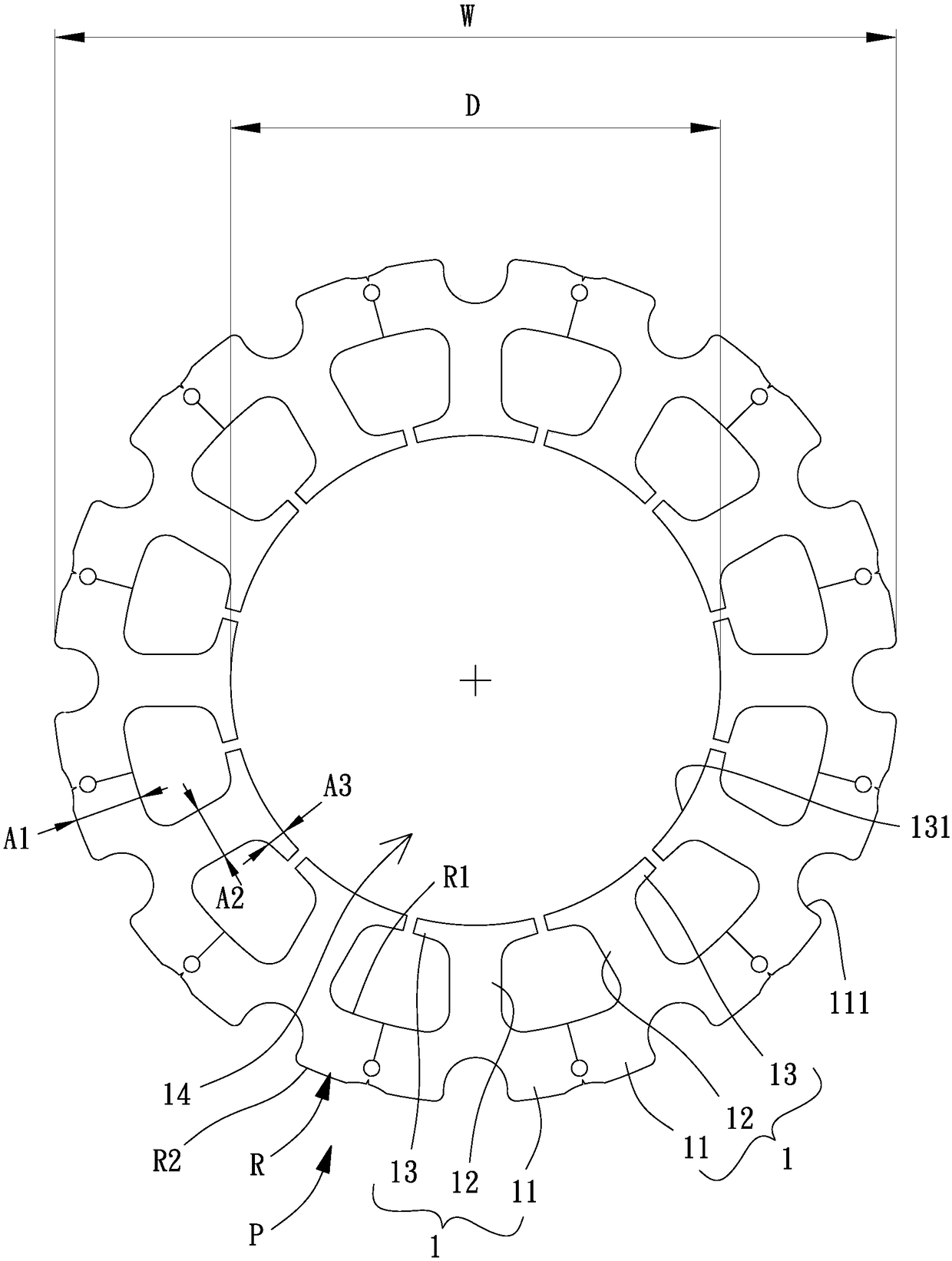
[0050] Please refer to figure 2 , 3 , which is the first embodiment of the silicon steel sheet P for the motor stator of the present invention, the silicon steel sheet P for the motor stator includes a plurality of connected magnetic pole units 1, each magnetic pole unit 1 has a yoke portion 11, a pole column part 12 and a pole shoe part 13; the yoke part 11, the pole part 12 and the pole shoe part 13 of each magnetic pole unit 1 can be integrally formed and connected, or assembled and connected by any method or structure, and the present invention is not limited .

[0051] In detail, the plurality of pole units 1 are connected by yoke parts 11 to form a yoke ring R; the number of pole parts 12 of the silicon steel sheet P can be a multiple of three, preferably at least twelve; each magnetic pole The pole part 12 of the unit 1 can expand the magnetic conduction area by the inner surface 131 of the connected pole shoe part 13, and form an accommodating hole 14 surrounded by ...


PUM


Abstract

The invention provides a silicon steel plate for a motor stator, in order to solve problems derived from bad configuration relation between inner diameter and outer diameter of a silicon steel plate in the prior art. A silicon steel plate used to form a stator of a motor is disclosed. The silicon steel plate includes a plurality of magnetic pole units. Each of the plurality of magnetic pole unitsincludes a magnetic yoke portion, a pole portion and a boost portion. The magnetic yoke portions of the plurality of magnetic pole units are connected as a magnetic yoke ring. The boost portion includes an inner face, and the inner faces of the boost portions of the plurality of magnetic pole units form a receiving hole. The receiving hole has a maximal diameter, the silicon steel plate has a maximal diameter, and a ratio of the maximal diameter of the receiving hole to the maximal diameter of the silicon steel plate is 0.54-0.84.

Description

technical field [0001] The invention relates to a motor part, especially a silicon steel sheet for a motor stator. Background technique [0002] Please refer to figure 1 , which is an existing silicon steel sheet 9 used in the motor stator, the silicon steel sheet 9 has a yoke ring 91, and the outer ring edge of the yoke ring 91 can be assembled to a motor base (not shown in the figure ), the inner edge of the yoke ring 91 is provided with a plurality of equiangularly distributed poles 92 for respectively winding a coil C; the end of each pole 92 extending toward the center is connected with a pole piece 93, The pole piece 93 is used to expand the magnetically permeable area of ​​the silicon steel sheet 9, and an accommodating hole 94 is formed surrounded by the inner surfaces of the plurality of pole pieces 93, and the accommodating hole 94 is used for accommodating a rotor (Fig. not shown). An embodiment similar to the existing silicon steel sheet 9 has been disclosed i...

Claims


Application Information

Patent Timeline
Patent Type & Authority Applications(China)
IPC IPC(8): H02K1/14
CPCH02K1/146H02K2213/03H02K1/2773H02K2201/03H02K1/02
Inventor 洪银树王启民刘家姈
Owner SUNONWEALTH ELECTRIC MACHINE IND
Why Eureka
Try Eureka