Power dissipation control method and camera device

A technology for camera device and power consumption control, which is applied in image communication, TV, color TV components and other directions, and can solve problems such as poor power consumption control effect.

Active Publication Date: 2018-06-12
YUNDING NETWORK TECH BEIJING
View PDF8 Cites 9 Cited by
  • Summary
  • Abstract
  • Description
  • Claims
  • Application Information

AI Technical Summary

Problems solved by technology

It can be seen that the power consumption control scheme of the existing network camera will still

Method used


Image

  • Power dissipation control method and camera device
  • Power dissipation control method and camera device
  • Power dissipation control method and camera device

Examples


Embodiment Construction

[0059] Exemplary embodiments of the present disclosure will be described in more detail below with reference to the accompanying drawings. Although exemplary embodiments of the present disclosure are shown in the drawings, it should be understood that the present disclosure may be embodied in various forms and should not be limited by the embodiments set forth herein. Rather, these embodiments are provided for more thorough understanding of the present disclosure and to fully convey the scope of the present disclosure to those skilled in the art.

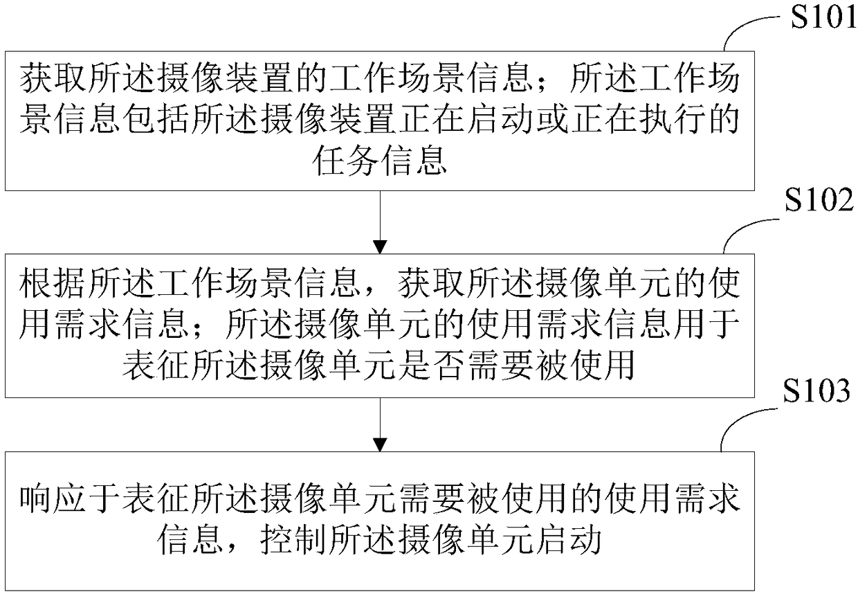
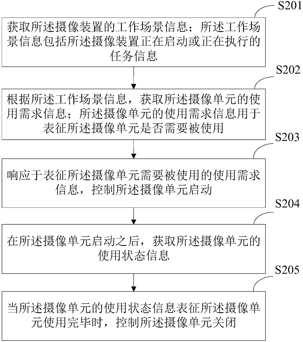
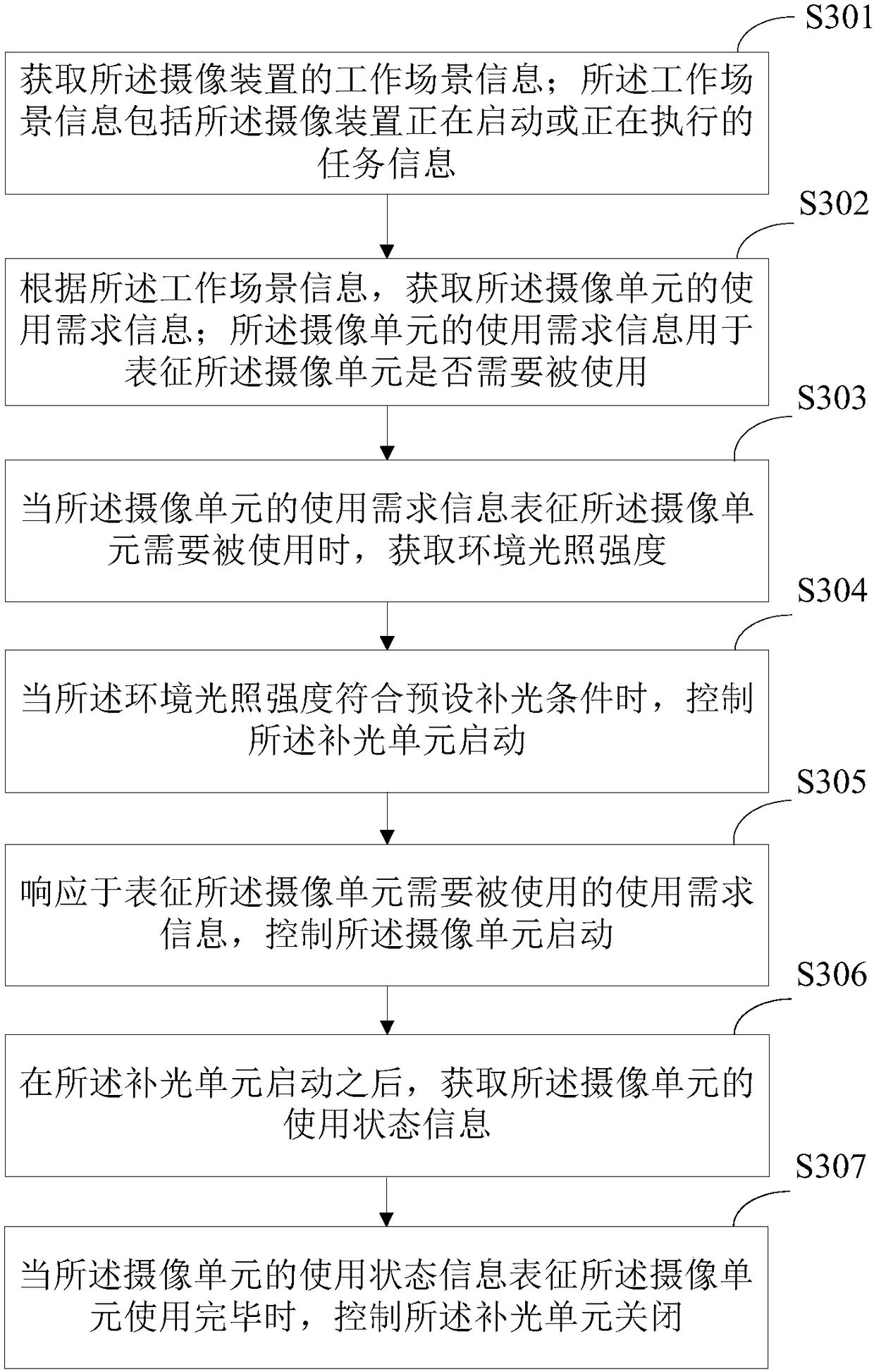
[0060] The power consumption control method provided by the present invention is applied to an imaging device, and the imaging device includes an imaging unit. The camera unit is in an off state, a low power consumption state, or a dormant state after the camera is started, and the off state, low power consumption state, and dormant state may be preset by the user or by the system. The closed state can specifically refer to the cam...


PUM


Abstract

The invention provides a power dissipation control method and a camera device. A camera unit in a camera device is under a closing state after starting the camera device. The method includes steps ofacquiring working scene information of the camera device; according to the working scene information, acquiring using demand information of the camera unit; when the using demand information of the camera unit represents that the camera unit is required to be used, controlling the startup of the camera unit. The camera unit only can be started under the working scene required to use, otherwise, the original closing state can be kept; thus the method effectively avoids the unnecessary power dissipation loss caused by starting the camera unit when the camera unit is not required to use, and further reduces the power dissipation level of the camera unit and improves the power dissipation control effect.

Description

technical field [0001] The invention relates to the field of automatic control, more specifically, to a power consumption control method and an imaging device. Background technique [0002] Smart peephole is a home security product that replaces the traditional peephole, and its essence is a network camera. In order to meet the security needs of the owners, the network cameras need to work continuously 24 hours a day, and the power consumption is high, especially the battery-powered network cameras, which have poor battery life, which in turn affects the user experience. [0003] A network camera (IPC, IP Camera) usually includes an IPC main module, a camera, an infrared supplementary light, a power consumption control module, a human body infrared sensor (PIR) module, and a WIFI module, among which the IPC main module and related peripheral devices are the main power consumption electrical part. At present, the commonly used power consumption control scheme is to use the ...

Claims


Application Information

Patent Timeline
IPC IPC(8): H04N5/232
CPCH04N23/65H04N23/651
Inventor 刘达生邓雄书陈卫亮陈彬张东胜
Owner YUNDING NETWORK TECH BEIJING
Why Eureka
Try Eureka