Method and system for providing adaptive timing recovery for low power application

a low-power application and adaptive timing technology, applied in the field of adaptive timing recovery, can solve the problems of high power consumption in electronic devices, conventional adaptive timing recovery generally requires significant power consumption, and low so as to reduce the execution rate of error function modules, reduce the rate of clock enable signals, and reduce the effect of error function modules

Active Publication Date: 2007-04-03
AVAGO TECH INT SALES PTE LTD
View PDF5 Cites 2 Cited by
  • Summary
  • Abstract
  • Description
  • Claims
  • Application Information

AI Technical Summary

Benefits of technology

[0008]In the steady mode, the error function module is directed to execute at a slower rate. In one exemplary embodiment, the lower execution rate of the error function module is achieved by decimating or reducing the rate of the clock enable signal generated by the fractional resampler. Since the error function module is driven by the clock enable signal, reducing the rate of the clock enable signal also reduces the execution rate of the error function module. By executing at a slower rate, the error function module is able to operate at a reduced level of power consumption.
[0009]In an exemplary application, the present invention can be deployed to reduce power consumption of the timing recovery loop used in a digital demodulator.

Problems solved by technology

Conventional adaptive timing recovery suffers from a number of problems.
For example, conventional implementation of adaptive timing recovery generally requires significant power consumption.
The myriad types of problems associated with high level of power consumption in electronic devices are well known.
In addition, conventional circuitry used to implement adaptive timing recovery does not scale well when multiple timing recovery loops are used on one chip for multiple channels.
Furthermore, such circuitry is unable to adapt the update rate based on timing loop lock status.

Method used


Image

  • Method and system for providing adaptive timing recovery for low power application
  • Method and system for providing adaptive timing recovery for low power application

Examples


Embodiment Construction

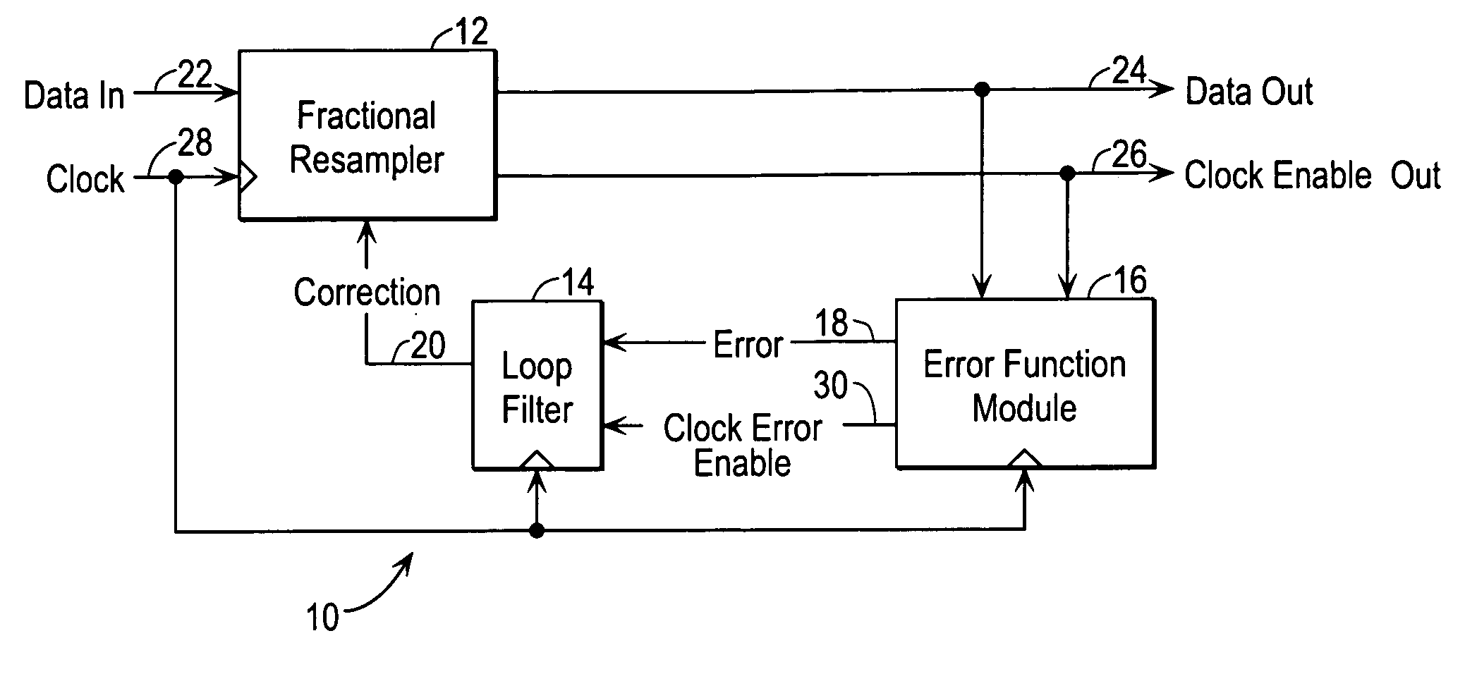
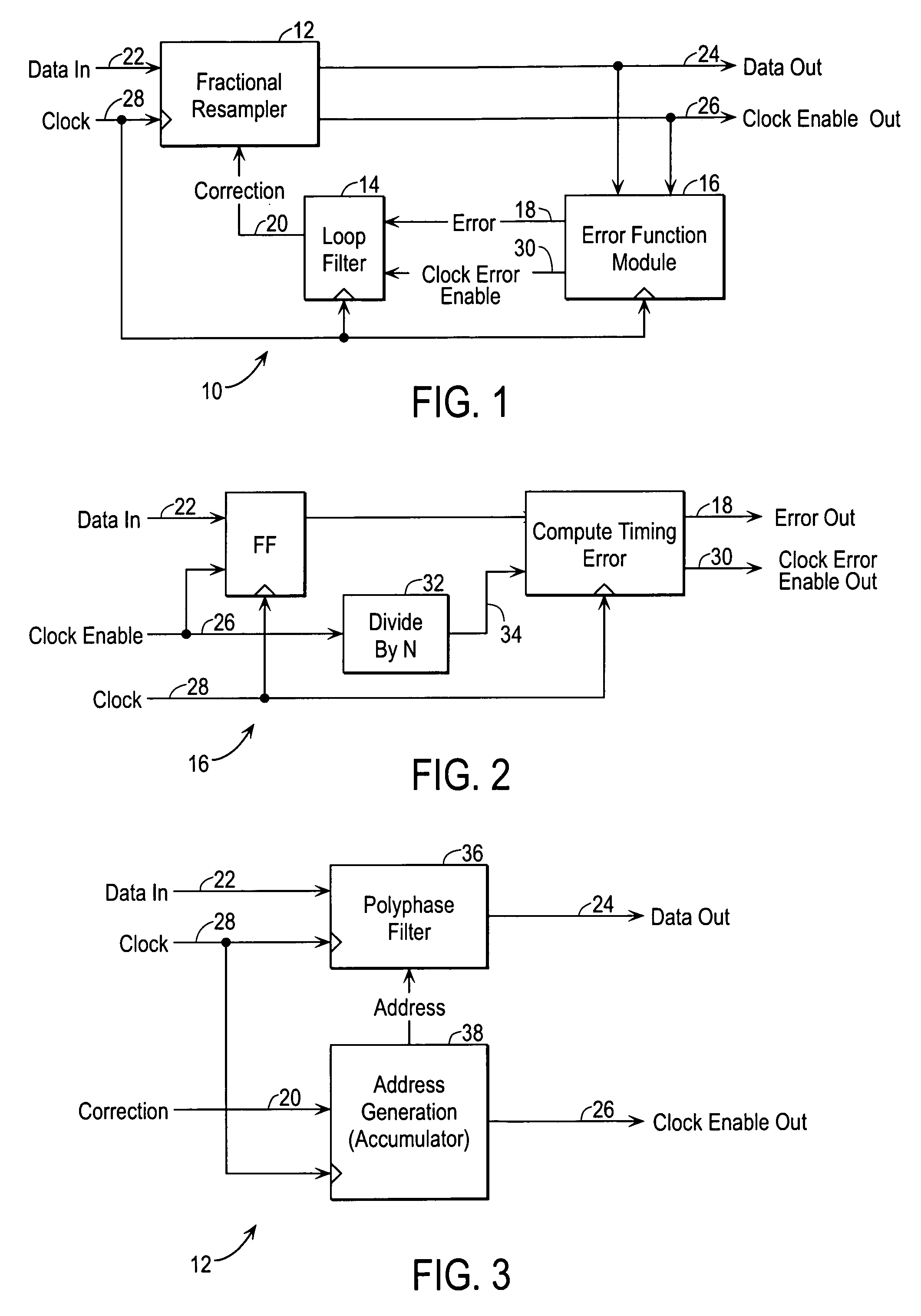
[0014]The present invention in the form of one or more exemplary embodiments will now be described. FIG. 1 is a simplified block diagram illustrating an exemplary embodiment of the present invention. Referring to FIG. 1, there is shown a system 10 that is capable of providing adaptive timing recovery in accordance with the present invention. The system 10 includes a fractional resampler 12, a loop filter 14 and an error function module 16. The fractional resampler 12, the loop filter 14 and the error function module 16 are arranged in a servo feedback configuration to form a timing recovery loop. A data signal 22 is provided to the fractional resampler 12. The fractional resampler 12 samples the data signal 22 and generates a sampled output 24. The sampled output 24 from the fractional resampler 12 is fed to the error function module 16. Output in the form of an error signal 18 from the error function module 16, in turn, is fed to the loop filter 14. The loop filter 14 then provides...


PUM


Abstract

A system for providing adaptive timing recovery is provided. In an exemplary embodiment, the system includes a fractional resampler, an error function module and a loop filter, arranged collectively to form a timing recovery loop. In an initial mode, the error function module compares the output of the fractional resampler with a reference signal to determine an error, if any. An error signal is generated accordingly based on the error. The error signal is then provided to the loop filter allowing the loop filter to generate a correction signal. The correction signal is provided to the fractional resampler to allow the fractional resampler to generate an output which minimizes the error. When the error function module determines that the error is within an acceptable range, i.e., a timing lock is achieved, the system goes into a steady mode. In the steady mode, the error function module is directed to execute at a slower rate. By executing at a slower rate, the error function module is able to operate at a reduced level of power consumption.

Description

CROSS-REFERENCES TO RELATED APPLICATION[0001]The present application claims the benefit of priority under 35 U.S.C. § 119 from U.S. Provisional Patent Application Ser. No. 60 / 329,245, filed Oct. 11, 2001, entitled “ADAPTIVE TIMING RECOVERY FOR LOW POWER APPLICATIONS”, by Stenerson et al., the disclosure of which is hereby incorporated by reference in its entirety for all purposes as if set forth in full herein.BACKGROUND OF THE INVENTION[0002]The present invention generally relates to adaptive timing recovery, and more specifically, to a method and system for providing improved adaptive timing recovery for low power applications.[0003]Adaptive timing recovery has been in use for years in electronic equipment. In a conventional piece of electronic equipment that utilizes adaptive timing recovery, adaptive timing recovery is typically accomplished using a full rate timing error generation function and a loop filter.[0004]Conventional adaptive timing recovery suffers from a number of p...

Claims


Application Information

Patent Timeline
Patent Type & Authority Patents(United States)
IPC IPC(8): H03D3/18H03D3/24
CPCH04L7/0029
Inventor STENERSON, ROGERZHANG, WEIMIN
Owner AVAGO TECH INT SALES PTE LTD
Why Eureka
Try Eureka