Electrostatic dust-removing glass, manufacturing method thereof, electrostatic dust-removing lens and camera equipment
An electrostatic dust removal and glass technology, which is used in electrostatic dust removal lenses and camera equipment, electrostatic dust removal glass and its manufacturing fields, can solve problems such as limited application scenarios and large voltage requirements, achieve strong dust removal capabilities, and improve practicability and application range. Effect
- Summary
- Abstract
- Description
- Claims
- Application Information
AI Technical Summary
Problems solved by technology
Method used
Image
Examples
Embodiment 1
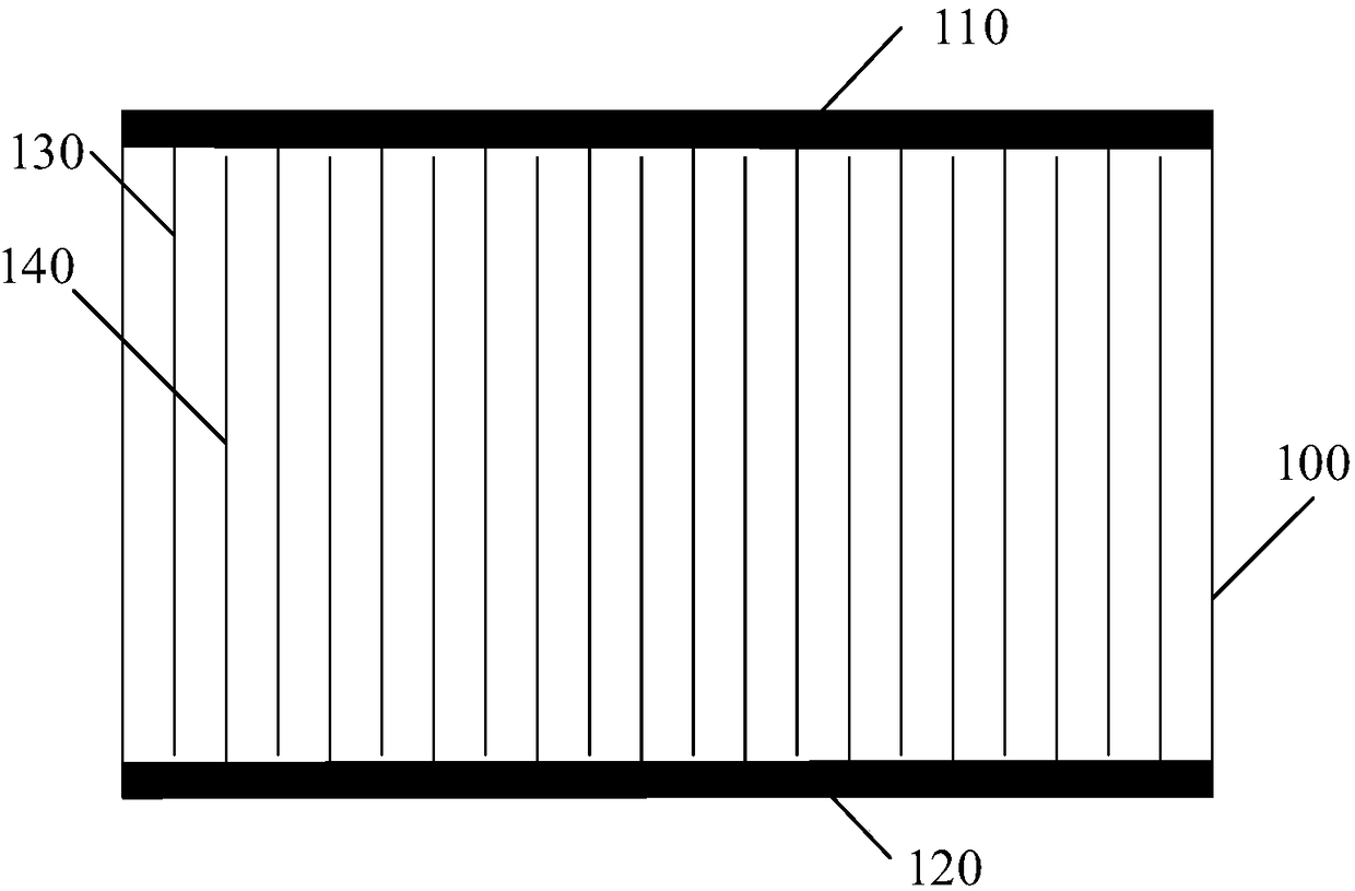
[0064] A layer of ITO with a thickness of 40 μm was deposited on the surface of the camera glass by vapor deposition. Then, the ITO coating on the glass surface is etched into conductive lines by using a screen etching method. The width of each conductive line is 10 μm, the distance between each conductive line is maintained at 500 μm, and the error of the width of the conductive line and the distance between the conductive lines is less than 0.5%.
[0065] Parallel positive and negative electrodes are plated on both sides of the glass, and multiple conductive wires are alternately connected to the positive and negative electrodes. Connect an external DC power supply to the electrodes with a voltage of 360V.
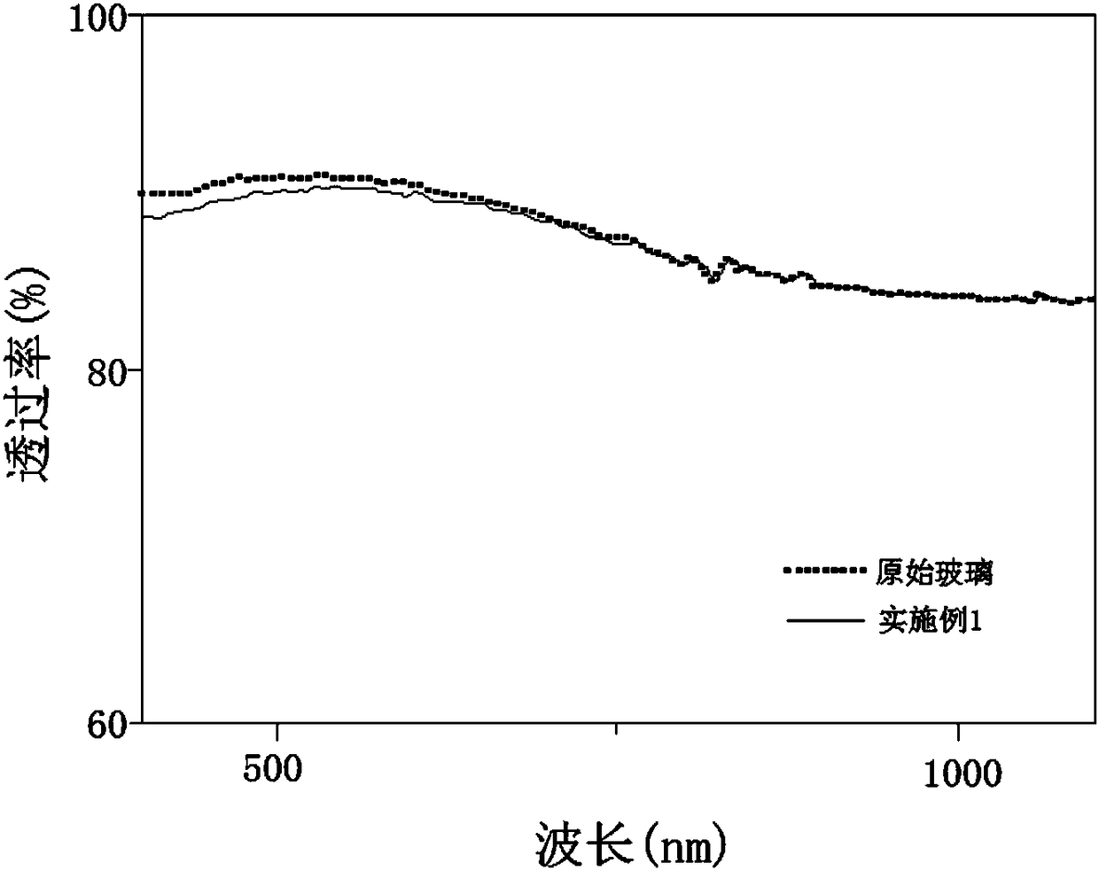
[0066] figure 2 A schematic diagram showing the comparison of transmittance between the electrostatic precipitating glass of this embodiment and the original glass is shown. Although the electrode lines and electrodes are formed on the glass, the light transmittance ...
Embodiment 2
[0069] A layer of ITO with a thickness of 50 μm was deposited on the surface of the camera glass by vapor deposition. Then, the ITO coating on the glass surface is etched into conductive lines by using a screen etching method. The width of each conductive line is 30 μm, the distance between each conductive line is maintained at 800 μm, and the error of the width of the conductive line and the distance between the conductive lines is less than 0.5%.
[0070] Parallel positive and negative electrodes are plated on both sides of the glass, and multiple conductive wires are alternately connected to the positive and negative electrodes. Connect the external DC power supply to the electrodes with a voltage of 240V.
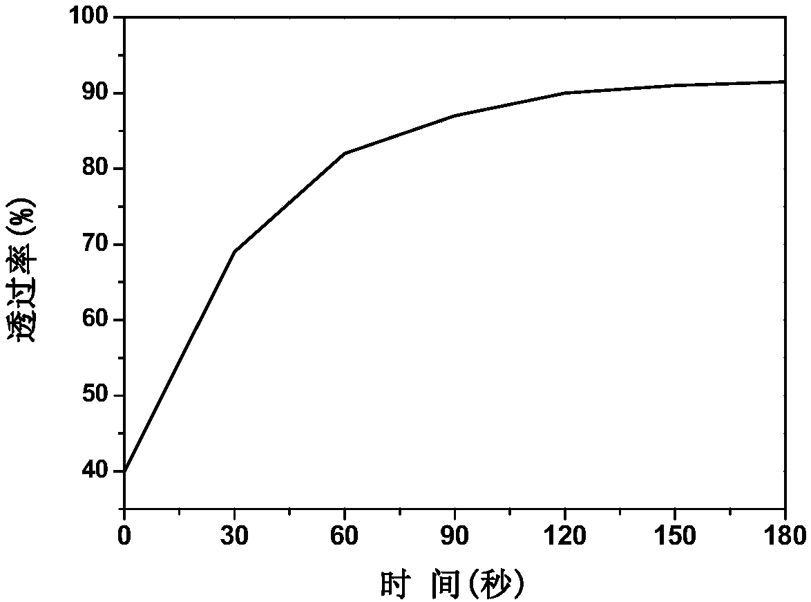
[0071] Use a sandblasting machine to deposit a layer of dust particles with a total weight of about 80g and dust particles of 20-200μm on the surface of the camera glass. After power-on, use a vertical spectrometer to measure the change of transmittance with time in t...
Embodiment 3
[0073] A layer of ITO with a thickness of 60 μm was deposited on the surface of the camera glass by vapor deposition. Then, the ITO coating on the glass surface is etched into conductive lines by using a screen etching method. The width of each conductive line is 50 μm, the distance between each conductive line is maintained at 1000 μm, and the error of the width of the conductive line and the distance between the conductive lines is less than 0.5%.
[0074] Parallel positive and negative electrodes are plated on both sides of the glass, and multiple conductive wires are alternately connected to the positive and negative electrodes. Connect an external DC power supply to the electrodes with a voltage of 120V.
[0075] Use a sandblasting machine to deposit a layer of dust particles with a total weight of about 80g and dust particles of 20-200μm on the surface of the camera glass. After power-on, use a vertical spectrometer to measure the change of transmittance with time in t...
PUM
| Property | Measurement | Unit |
|---|---|---|
| Width | aaaaa | aaaaa |
| Width | aaaaa | aaaaa |
Abstract
Description
Claims
Application Information
 - R&D
- Intellectual Property
- Life Sciences
- Materials
- Tech Scout
- Unparalleled Data Quality
- Higher Quality Content
- 60% Fewer Hallucinations
Browse by: Latest US Patents, China's latest patents, Technical Efficacy Thesaurus, Application Domain, Technology Topic, Popular Technical Reports.
© 2025 PatSnap. All rights reserved.Legal|Privacy policy|Modern Slavery Act Transparency Statement|Sitemap|About US| Contact US: help@patsnap.com


