Multi-thread laser power measuring device suitable for laser aging test

A test device and laser power technology, applied in the electronic field, can solve the problems of manpower consumption, increase production cost, and reduce production efficiency, and achieve the effects of improving applicability, reducing loss, and improving controllability

Active Publication Date: 2021-09-21
江苏亮点光电研究有限公司
View PDF7 Cites 2 Cited by
  • Summary
  • Abstract
  • Description
  • Claims
  • Application Information

AI Technical Summary

Problems solved by technology

[0002] According to the requirements of military equipment automation and intelligence, a large number of optoelectronic equipment (as large as laser weapons, as small as single-soldier aiming range finder) is used in the military field, requiring the production units or departments of military optoelectronic preparations to produce military equipment with low cost and high efficiency. Photoelectric equipment and military equipment must first meet the environmental requirements. Mass-produced military equipment consumes a lot of manpower in the environmental testing process, which reduces production efficiency and increases production costs. The purpose of this invention is to use a laser power meter to Simultaneously monitor the output power of a dozen or dozens of lasers working under different environmental conditions, greatly reducing the time required for environmental testing, reducing the equipment cost of purchasing laser power meters and the labor cost of manual measurement. Therefore, the present invention designs a A multi-threaded laser power measurement device suitable for laser aging testing to solve the problems in the prior art

Method used


Image

  • Multi-thread laser power measuring device suitable for laser aging test
  • Multi-thread laser power measuring device suitable for laser aging test
  • Multi-thread laser power measuring device suitable for laser aging test

Examples


Embodiment Construction

[0025] The technical solutions in the embodiments of the present invention will be clearly and completely described below in conjunction with the accompanying drawings in the embodiments of the present invention. Obviously, the described embodiments are only some of the embodiments of the present invention, not all of them. Based on the embodiments of the present invention, all other embodiments obtained by persons of ordinary skill in the art without creative work all belong to the protection scope of the present invention.

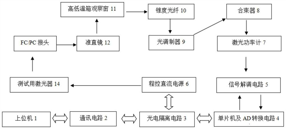
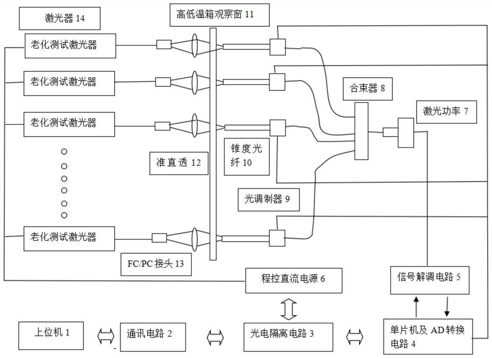
[0026] 5. See Figure 1-6 , an embodiment provided by the present invention: a multi-threaded laser power measurement device suitable for laser aging testing, the present invention is applicable to host computer 1, communication circuit 2, photoelectric isolation circuit 3, single-chip microcomputer and AD conversion circuit 4, signal Demodulation circuit 5, programmable DC power supply 6, laser power meter 7, beam combiner 8, optical modulator 9, tapere...


PUM


Abstract

The invention discloses a multi-thread laser power measuring device suitable for a laser aging test. The multi-thread laser power measuring device comprises an upper computer, a communication circuit, a photoelectric isolation circuit, a single-chip microcomputer and AD conversion circuit, a signal demodulation circuit, a program-controlled direct-current power supply, a laser power meter, a beam combiner, an optical modulator, a taper optical fiber, a high-low temperature box observation window, a collimating lens, an FC / PC connector and a test laser. Meanwhile, the program-controlled direct-current power supply sends the collected electrical parameters of each laser to the upper computer through the photoelectric isolation circuit and the communication circuit. According to the invention, output energy of laser can be effectively transmitted out of the high and low temperature box body through the collimating lens, the high and low temperature box window with a special process and the taper optical fiber, the test hardware can meet the requirement that the output power of a plurality of test lasers can be simultaneously acquired by software multithreading, and the optical pulse is arbitrarily set from 0.01 H to 10GHz; the direct-current power supply can be provided with three kinds of settings,: steady current, steady voltage and temperature power, the interfaces are abundant, the communication circuit supports an RS232 interface, an RS485 interface and a CAN bus interface, and the use is convenient and simple.

Description

technical field [0001] The invention relates to a multi-thread testing device in a high and low temperature environment, in particular to a device suitable for military high and low temperature environments, which uses one testing device to simultaneously test multiple testing devices, and belongs to the field of electronic technology. Background technique [0002] According to the requirements of military equipment automation and intelligence, a large number of optoelectronic equipment (as large as laser weapons, as small as single-soldier aiming range finder) is used in the military field, requiring the production units or departments of military optoelectronic preparations to produce military equipment with low cost and high efficiency. Photoelectric equipment and military equipment must first meet the environmental requirements. Mass-produced military equipment consumes a lot of manpower in the environmental testing process, which reduces production efficiency and increas...

Claims


Application Information

Patent Timeline
IPC IPC(8): G01M11/02
CPCG01M11/0207
Inventor 蔡震李清华
Owner 江苏亮点光电研究有限公司
Why Eureka
Try Eureka