Centered guiding device of bars for straightening machine

A straightening machine bar and guide device technology, applied in the direction of feeding device, positioning device, storage device, etc., can solve the vibration of the guide plate door and the large increase in the activity range, the guide plate door cannot be effectively locked, and cannot meet the production requirements, etc. problems, to achieve the effect of reducing vibration and activity intervals, reducing oil leakage failures, and reducing maintenance costs

Pending Publication Date: 2018-06-15
SHIJIAZHUANG IRON & STEEL
View PDF8 Cites 6 Cited by
  • Summary
  • Abstract
  • Description
  • Claims
  • Application Information

AI Technical Summary

Problems solved by technology

[0004] 1. The cylinder body of the locking cylinder is fixed on the overall frame of the straightening machine, and the piston rod is pushed against the guide plate door. Due to the small size and light weight of the piston rod, when the guide plate door is subjected to a large impact during the operation of the straightener , the piston rod is easy to vibrate violently with the guide plate door, resulting in oil leakage from the locking cylinder, which not only increases the maintenance cost of the equipment, but also seriously affects the normal production
[0005] 2. The piston rods of the two locking cylinders press the guide plate door from the left and right sides respectively. The contact surface between the piston rod and the guide plate door is a plane perpendicular to the axis of the piston rod. The friction between the piston rod and the guide plate door is used to prevent the guide plate from The door swings to the outside, and the guide door cannot be effectively locked, especially when producing large-scale bars with large curvature and high yield strength, the vibration and movable range of the guide door will increase greatly, and the straightening accuracy of the bar will drop significantly. unable to meet production requirements

Method used


Image

  • Centered guiding device of bars for straightening machine
  • Centered guiding device of bars for straightening machine
  • Centered guiding device of bars for straightening machine

Examples


Embodiment Construction

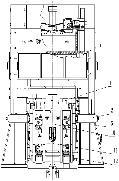
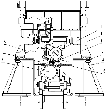
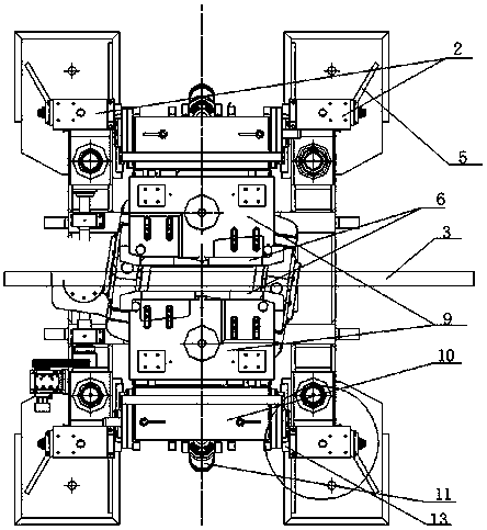
[0024] see Figure 1 to Figure 5 , the main body of the straightener (excluding the main motor and drive shaft) includes: the overall frame of the straightener (including the base of the straightener, the prestressed frame 4 of the straightener and the prestressed column 8 of the straightener), the upper straightening roller 1. The lower straightening roller 7 and the bar centering guide device, wherein the bar centering guide device mainly includes two bar limit units, and each bar limit unit includes a locking cylinder 2 and a guide bar 6 , guide guard plate 9, guide plate door 10, hydraulic support rod 11, rotating shaft 12, guide sleeve 18 and positioning block 19. The guide strip 6 is installed and fixed on the innermost side of the guide plate 9, and can be replaced. The guide strip 6 will be in contact with the bar to ensure that the bar is centered.

[0025] The two-roller straightening machine has two upper and lower straightening rollers. The upper straightening rol...


PUM


Abstract

The invention discloses a centered guiding device of bars for a straightening machine. The centered guiding device comprises two bar limiting units symmetrically arranged on the two sides of a roll gap, wherein each bar limiting unit comprises a guiding plate door, a guiding strip, a guiding plate and two locking cylinders; the lower part of each of the guiding plate doors is rotatably connected with a straightening machine base through a rotating shaft; each of the guiding strips is blocked on the side part of the roll gap and is connected with each of the guiding plate doors through each ofthe guiding plates; the two locking cylinders are respectively positioned on the left side upper part and the right side upper part of each of the guiding plate doors; and cylinder bodies of the locking cylinders are supported on each of the guiding plate doors. According to the centered guiding device of the bars for the straightening machine disclosed by the invention, the guiding plate doors are pressed tightly by the cylinder bodies of the locking cylinders, and because the mass of the cylinder bodies is large, slight vibration is only produced when the guiding plate doors are impacted, sothat sealing of the locking cylinders is difficultly damaged; and therefore, oil leakage failure is reduced, the operation reliability of the centered guiding device is improved, the maintenance costof the equipment is reduced, and a normal operation of production is ensured.

Description

technical field [0001] The invention relates to a bar centering and guiding device used on a bar straightening machine, which belongs to the technical field of metal bar machining. Background technique [0002] The process flow of the bar finishing line is: feeding → straightening → chamfering → shot blasting → surface and internal flaw detection → collection → bundling → weighing and storage. As an important equipment of the whole finishing line, the straightening machine is used in the first finishing process, which plays an important role in ensuring the straightness of the bar, facilitating the processing of the subsequent process, and improving the processing accuracy of the subsequent process. The two-roll straightening machine is a kind of equipment with concave and convex straightening rollers of hyperbolic roll type as the core component, and uses the principle of three-point inversion to straighten the round bar. Its straightening accuracy is high, but the straight...

Claims


Application Information

Patent Timeline
Patent Type & Authority Applications(China)
IPC IPC(8): B21D43/00B21D3/02
CPCB21D3/02B21D43/006
Inventor 聂志水封桂祥阎岩刘建培周立波常鹏飞华祺年何少松李宁尹飞
Owner SHIJIAZHUANG IRON & STEEL
Why Eureka
Try Eureka