
Mounting tool for a super-large type door leaf

It is a technology for installing tooling and oversize, which is applied in metal processing, manufacturing tools, metal processing equipment, etc. It can solve the problems of large manpower and material resources, low efficiency, and inability to use cranes, so as to reduce the probability of stress concentration and ensure stability. , Increase the effect of the scope of application

Pending Publication Date: 2018-06-15
CHINA NUCLEAR IND 24 CONSTR
View PDF0 Cites 0 Cited by
  • Summary
  • Abstract
  • Description
  • Claims
  • Application Information

AI Technical Summary

Problems solved by technology

However, when the room or space is limited, heavy-duty flatbed trucks and cranes cannot be used. As a result, the movement and installation of extra-large door leaves can only be carried out by primitive methods, such as "rolling wood" to move, and then use hoisting hoists to lift and install. Low and requires a lot of manpower and material resources

Method used


Image

  • Mounting tool for a super-large type door leaf
  • Mounting tool for a super-large type door leaf
  • Mounting tool for a super-large type door leaf

Examples


Embodiment 1

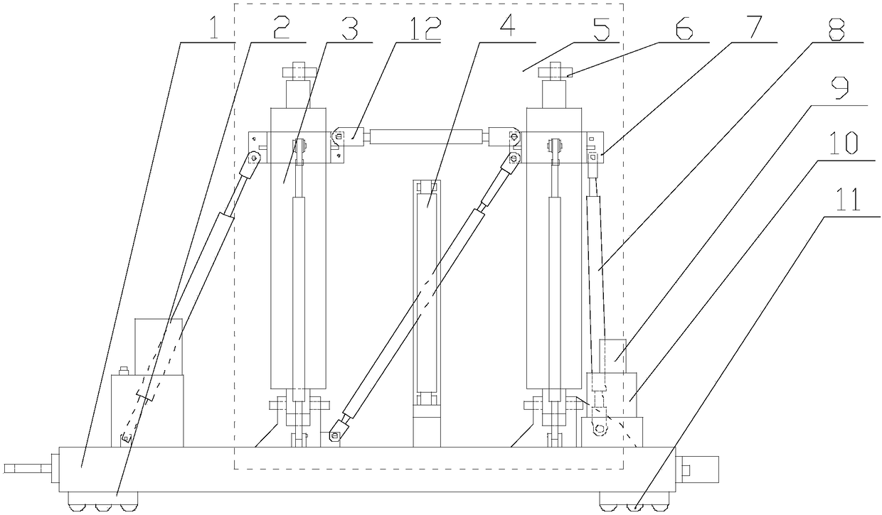
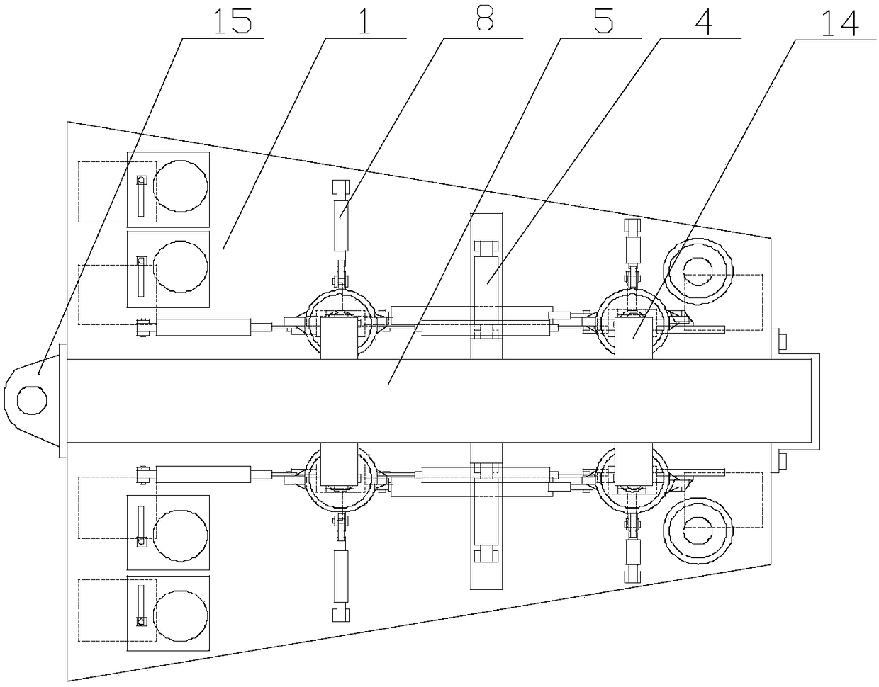
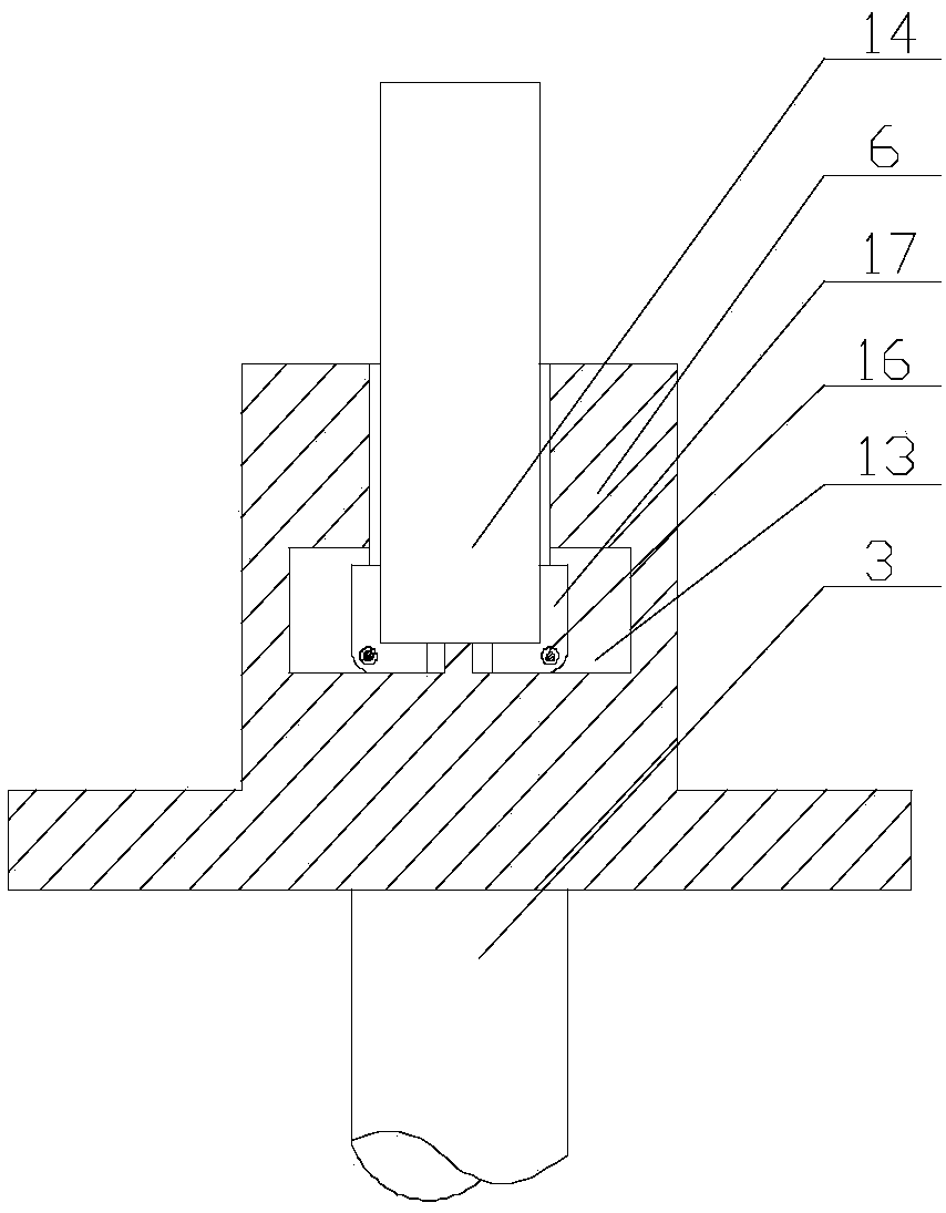
[0025] Such as Figure 1~3 As shown, the present embodiment includes a base 1, four oil cylinders 3 are arranged on the upper surface of the base 1, and a support head 6 is provided on the output end of each of the oil cylinders 3, and a limited opening is opened inside the support head 6. Position cavity 13, on the upper end surface of support head 6, there is a card slot communicating with limit cavity 13. The wall is provided with a central shaft 16, and the L-shaped block 17 is arranged on the central shaft 16 by a torsion spring. The ends of the horizontal sections of the two blocks 17 are oppositely arranged, and the position of the limiting cavity 13 in the horizontal direction The length is greater than the width of the clamping groove in the horizontal direction; in the initial state, the horizontal section of the clamping block 17 forms an acute angle with the bottom surface of the limiting cavity 13, when the output end of the oil cylinder 3 pushes the lifting lug ...

Embodiment 2

[0028] Such as Figure 1~3 As shown, in this embodiment, a snap ring 7 is provided on the upper outer peripheral wall of each of the oil cylinders 3, and a plurality of diagonal struts 8 are hingedly arranged on the base 1, and the upper ends of the diagonal struts 8 Hinged with the clasp 7, each of the diagonal struts 8 forms an acute angle with the upper surface of the base 1, and a boss is hinged on the upper surface of the base 1, and the bottom of the oil cylinder 3 is hinged with the upper end of the boss. Further, due to the different models and sizes of the door leaf 5, in order to ensure that the door leaf 5 can maintain a stable clamped state during the movement or transfer process, the applicant provided a boss on the base 1, while the oil cylinder 3 The snap ring 7 is installed in the upper part of the door, and the snap ring 7 and the oil cylinder 3 are supported and fixed by a plurality of length-adjustable diagonal struts 8, that is, according to the specific mo...

Embodiment 3

[0032] Such as Figure 1~3 As shown, the present embodiment also includes two right-angled triangular brackets 4, two guide rails are symmetrically arranged on the upper surface thereof along the mid-perpendicular line of the base 1, and the bracket 4 is slidably arranged on the guide rails, and on the base 1 A baffle is arranged on the baffle, and a screw hole is provided on the baffle, and the screw rod is connected with the bracket 4 after passing through the screw hole; Further, two triangular brackets 4 are arranged on the upper surface of the base 1, that is, before the door leaf 5 is hoisted and placed on the base 1, the distance between the two brackets 4 is greater than the thickness of the door leaf 5, when the door leaf 5 is placed on the base 1 , by turning the screw rod, the two brackets 4 are moved to the two side walls of the door leaf 5 respectively, until a right-angled side of the leg remains in close contact with the side walls of the door leaf 5 .

[0033]...


PUM


Abstract

The invention discloses a mounting tool for a super-large type door leaf. The mounting tool for the super-large type door leaf comprises a base; four cylinders are arranged on the upper surface of thebase, the output end of each cylinder is provided with a supporting head, the upper end face of each supporting head is provided with a clamping groove communicating with a limiting cavity, two sidewalls of each limiting cavity are provided with center shafts, clamping blocks are arranged on the center shafts through torsion springs, the end portions of the horizontal sections of every two clamping blocks are oppositely arranged, and the length of the limiting cavities in the horizontal direction is greater than the width of the clamping grooves in the horizontal direction. In order to solvethe problems that in the field of nuclear power plant building construction, when the super-large type door leaf is installed, especially when a shielding door leaf is installed in a narrow area, neither a large lifting machine nor a heavy-duty flat wagon can transfer and lift the door leaf, consequently a traditional labor transportation mode wasting both time and labor can only be adopted, andthus the mounting cost of the door leaf is high, the mounting tool special for transferring and mounting the heavy-duty door leaf is designed and is suitable for mounting the door leaf in the narrow area.

Description

technical field [0001] The invention relates to the field of nuclear power plant construction, in particular to a tool for installing an extra-large door leaf. Background technique [0002] Nuclear power plants often use extra-large screen doors, each weighing more than ten tons, and are generally moved and installed by heavy-duty flatbed trucks and cranes. However, when the room or space is limited, heavy-duty flatbed trucks and cranes cannot be used. As a result, the movement and installation of extra-large door leaves can only be carried out by primitive methods, such as "rolling wood" to move, and then use hoisting hoists to lift and install. Low, and need to invest a lot of manpower and material resources. Contents of the invention [0003] The purpose of the present invention is to provide a super-large door leaf installation tool to facilitate the installation of heavy door leaves. [0004] The present invention realizes through following technical scheme: [000...

Claims


Application Information

Patent Timeline
IPC IPC(8): B23P19/00
CPCB23P19/00
Inventor 赵新龙郭现玲李庆展刘畅张炳畅张益孙晓刘爱迪吴刚磊李强王成龙于岩松
Owner CHINA NUCLEAR IND 24 CONSTR
Features
  • Generate Ideas
  • Intellectual Property
  • Life Sciences
  • Materials
  • Tech Scout
  • Unparalleled Data Quality
  • Higher Quality Content
  • 60% Fewer Hallucinations
Learn More