Eureka AIR delivers breakthrough ideas for toughest innovation challenges, trusted by R&D personnel around the world.

Clamp for clamping rear cover of electric generator

A generator and fixture technology, applied in clamping, manufacturing tools, metal processing mechanical parts, etc., can solve the problems of difficult clamping and positioning of the back cover of the generator, affecting the processing accuracy of the product, and simple structure, so as to achieve accurate positioning. , Guarantee the effect of turning accuracy and clamping stability

Inactive Publication Date: 2018-06-15
佛山杰致信息科技有限公司
View PDF0 Cites 0 Cited by
  • Summary
  • Abstract
  • Description
  • Claims
  • Application Information

AI Technical Summary

Problems solved by technology

[0003] The structure of the back cover of the generator is complicated. In the processing process such as turning, the existing fixture structure is simple, and it is difficult to form an effective clamping and positioning for the back cover of the generator. The deviation of the positioning will affect the processing accuracy of the product, and even cause The product is scrapped, so we designed a fixture for clamping the back cover of the generator to solve the above problems

Method used


Image

  • Clamp for clamping rear cover of electric generator
  • Clamp for clamping rear cover of electric generator
  • Clamp for clamping rear cover of electric generator

Examples


Embodiment Construction

[0020] The following will clearly and completely describe the technical solutions in the embodiments of the present invention with reference to the accompanying drawings in the embodiments of the present invention. Obviously, the described embodiments are only some, not all, embodiments of the present invention.

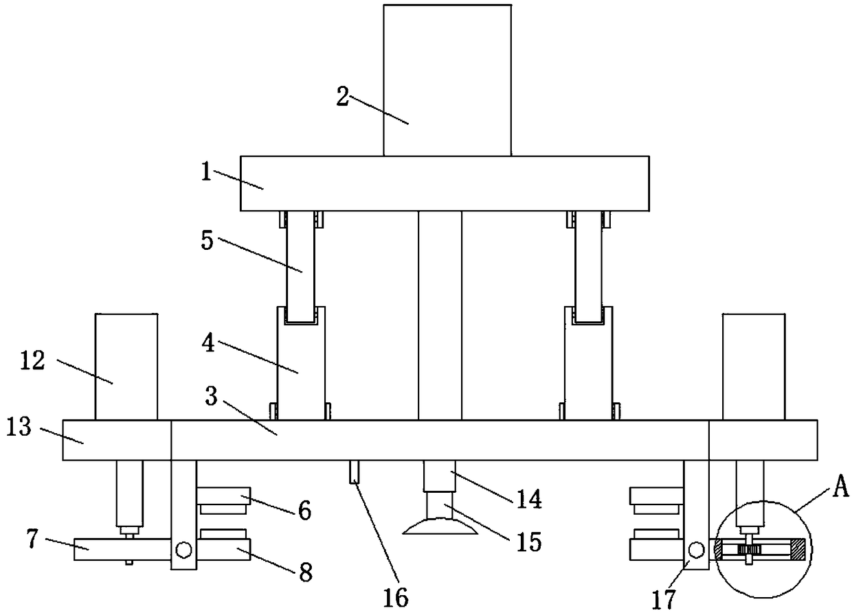
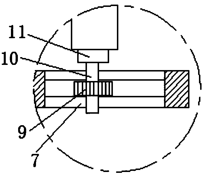
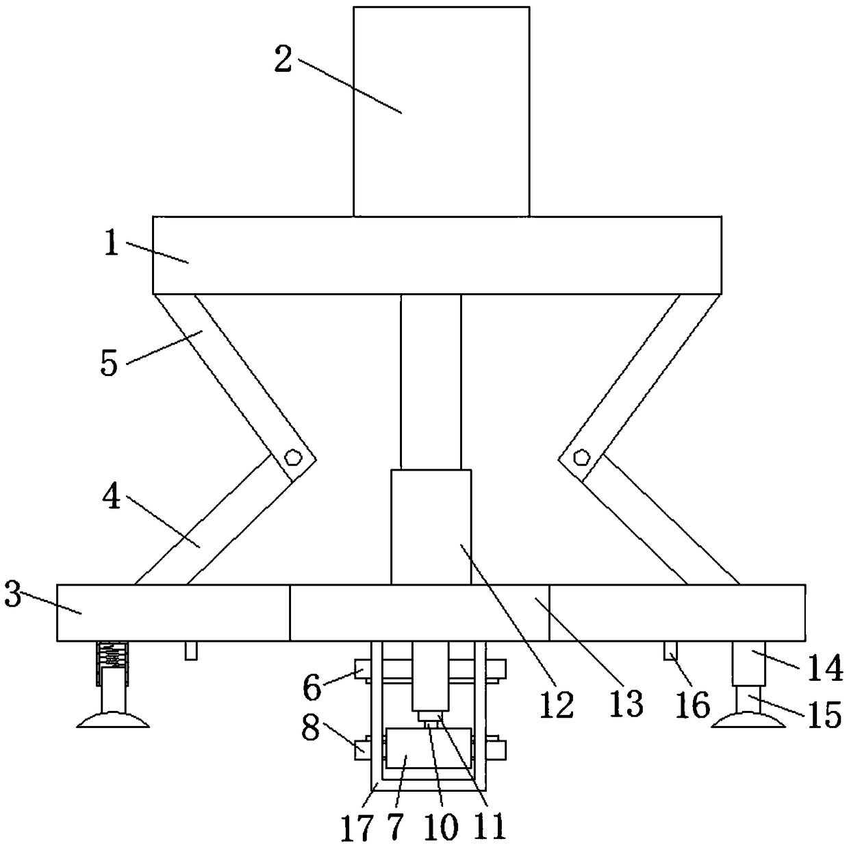
[0021] refer to Figure 1-4 , a fixture for clamping the back cover of the generator, including a fixed plate 1, a first cylinder 2 is provided on one side of the fixed plate 1, and the output end of the first cylinder 2 passes through one end of the fixed plate 1 and is vertically connected with a movable plate 3 , the side of the moving plate 3 close to the fixed plate 1 is rotatably connected with four sets of first connecting rods 4, and the end of the four groups of first connecting rods 4 away from the moving plate 3 is rotatably connected with a second connecting rod 5, and the second connecting rod 5 is away from One end of the first connecting rod 4 is conne...


PUM


Abstract

The invention discloses a clamp for clamping a rear cover of an electric generator. The clamp comprises a fixed plate, a first air cylinder is arranged on one side of the fixed plate, and the output end of the first air cylinder penetrates through one end of the fixed plate to be perpendicularly connected with a movable plate; four sets of first connecting rods are rotatably connected to the side,close to the fixed plate, of the movable plate; second connecting rods are rotatably connected to the ends, away from the movable plate, of the four sets of first connecting rods; the ends, away fromthe first connecting rods, of the second connecting rods are rotatably connected with the fixed plate; U-shaped rods are perpendicularly connected to the two ends of the side, away from the first connecting rods, of the movable plate correspondingly; and openings of the U-shaped rods face the movable plate. According to the clamp for clamping the rear cover of the electric generator, the structure is simple, design is reasonable, clamping of the rear cover through an upper clamping plate and a lower clamping plate is realized by utilizing extending and retracting of a second air cylinder, a suction cup and a positioning column are utilized to position the rear cover, the balance of the rear cover is kept, grabbing and positioning of the rear cover are realized quickly and stably, and themachining efficiency and precision are ensured.

Description

technical field [0001] The invention relates to the field of power generation devices, in particular to a clamp for clamping a generator back cover. Background technique [0002] A generator (English name: Generators) is a mechanical device that converts other forms of energy into electrical energy. It is driven by a water turbine, steam turbine, diesel engine or other power machinery, and converts the energy generated by water flow, air flow, fuel combustion or nuclear fission into mechanical energy. Passed to the generator, and then converted into electrical energy by the generator. Generators are widely used in industrial and agricultural production, national defense, science and technology and daily life. [0003] The structure of the back cover of the generator is complicated. In the process of turning and other processing, the existing fixture structure is simple, and it is difficult to form an effective clamping and positioning of the back cover of the generator. The...

Claims


Application Information

Patent Timeline
Patent Type & Authority Applications(China)
IPC IPC(8): B23Q3/08B23Q1/25
CPCB23Q3/088B23Q1/25
Inventor 王玉环
Owner 佛山杰致信息科技有限公司
Why Eureka
Eureka Blog
Learn More