Power cable taking-up and paying-off machine

A technology for take-up and pay-off machines and power cables, which is applied in the direction of overhead lines/cable equipment, etc., can solve the problems of poor versatility of pay-off barrels, reduce the difficulty of adjustment, increase the adjustment range, and reduce labor intensity.

Active Publication Date: 2018-06-15
中国电建集团河北工程有限公司
View PDF7 Cites 2 Cited by
  • Summary
  • Abstract
  • Description
  • Claims
  • Application Information

AI Technical Summary

Problems solved by technology

[0004] Aiming at the defects of poor versatility of pay-off barrels existing in the prior art, the present invention provides a power cable take-up and pay-off machine, which can adjust the size of the wire barrel according to needs, so that a set of The pay-off equipment is suitable for cable pay-off requirements of various specifications, which greatly improves the versatility and pay-off efficiency of the equipment

Method used


Image

  • Power cable taking-up and paying-off machine
  • Power cable taking-up and paying-off machine
  • Power cable taking-up and paying-off machine

Examples


Embodiment 1

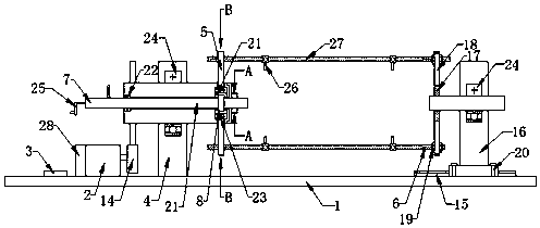
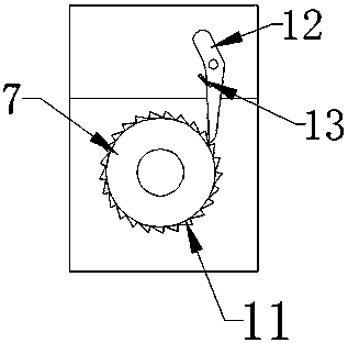
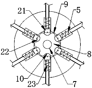
[0031] This embodiment, as the best embodiment of the present invention, discloses a power cable take-up and pay-off machine, the specific structure is as follows Figure 1 to Figure 3 As shown, it includes a frame 1, the frame 1 is provided with a connected motor 2 controller 3, and the motor 2 is provided with a motor brake 28; the frame 1 is provided with a left base 4 through rolling bearing 24 rotation, so One side of the left base 4 is provided with an end cover 30, and the left base 4 is slidably provided with an adjusting rod 7 and at least four sliding rods 5, and the adjusting rod 7 and the sliding rods 5 are respectively provided with an adjusting block 8 and a limit position. Block 21, the limit block 21 is rotated to be provided with roller 22, on the said adjusting fast 8, the supporting teeth 9 and the draw-in groove 10 are interlacedly arranged, and the said roller 22 is matched with the draw-in groove 10; The left base 4 is provided with a ratchet 11 and a paw...


PUM


Abstract

The invention discloses a power cable taking-up and paying-off machine. The power cable taking-up and paying-off machine comprises a rack. The rack is provided with a motor and a controller which areconnected. The power cable taking-up and paying-off machine is characterized in that the rack is rotationally provided with a left base, the left base is provided with a plurality of sliding rods in asliding manner, and the sliding rods are provided with supporting rods; the left base is further provided with an adjusting rod in a sliding manner, the adjusting rod is provided with an adjusting block, the adjusting block is provided with shoring teeth and clamping grooves, the shoring teeth and the clamping grooves are arranged in a staggered manner, and the clamping grooves are matched with the sliding rods; the adjusting rod and the left base are further provided with a ratchet and a pawl which are matched with each other, and a tension spring is connected between the pawl and the left base; and a transmission gear connected with the motor is arranged on the outer circumference of the left base. According to the power cable taking-up and paying-off machine, the size of a bobbin can be adjusted according to needs, accordingly, one paying-off device can meet the paying-off requirement of multiple specifications of cables, and the universality and the paying-off efficiency of the device are greatly improved.

Description

technical field [0001] The invention relates to the technical field of electric power equipment, in particular to a power cable retracting and unwinding machine. Background technique [0002] In the construction process of electric power facilities, a large number of cables of various specifications need to be laid. In the prior art, a pay-off device is generally used for the unwinding operation. However, due to the inconsistent specifications of the cables, the sizes of the various coils are inconsistent. It is often necessary to prepare pay-off spools of various specifications, which is not only cumbersome to replace the spools, but also inconvenient to carry the spools. [0003] The Chinese invention patent with the publication number CN204633224U discloses a power cable pay-off device, which includes an underframe, wheels are installed on both sides of the underframe, and two left and right stands are arranged on the underframe. There is a fixed baffle on the frame, and...

Claims


Application Information

Patent Timeline
Patent Type & Authority Applications(China)
IPC IPC(8): B65H75/44H02G1/02
CPCB65H75/44B65H75/4457B65H75/4486B65H2701/34H02G1/02
Inventor 史建平
Owner 中国电建集团河北工程有限公司
Why Eureka
Try Eureka