a supporting device

A supporting device and bearing technology, which is applied in the field of mechanical devices and can solve the problems of low structural strength of the supporting device

Active Publication Date: 2020-01-31
WUHAN MARINE MACHINERY PLANT
View PDF3 Cites 0 Cited by
  • Summary
  • Abstract
  • Description
  • Claims
  • Application Information

AI Technical Summary

Problems solved by technology

[0006] In order to solve the problem of low structural strength of the supporting device, the embodiment of the present invention provides a supporting device

Method used


Image

  • a supporting device
  • a supporting device
  • a supporting device

Examples


Embodiment

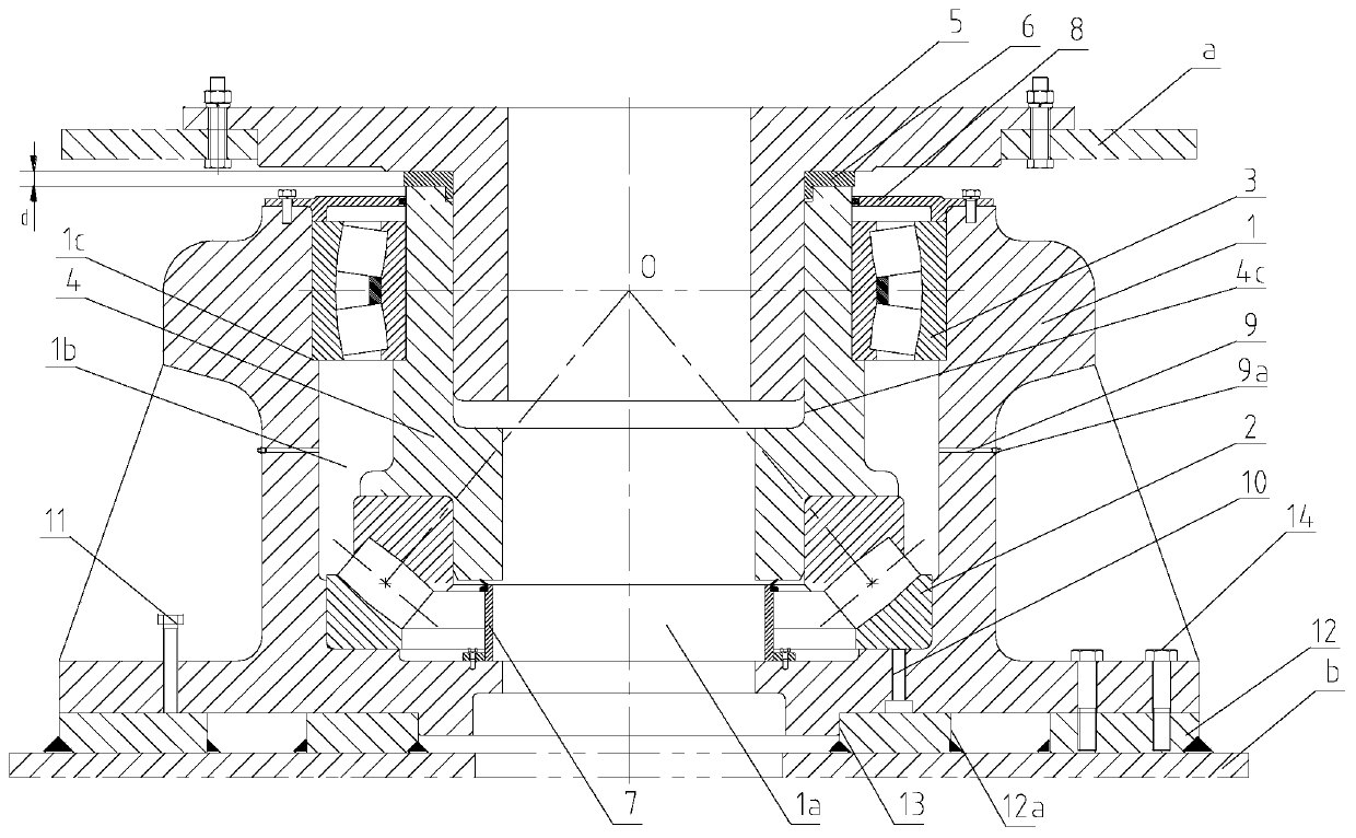
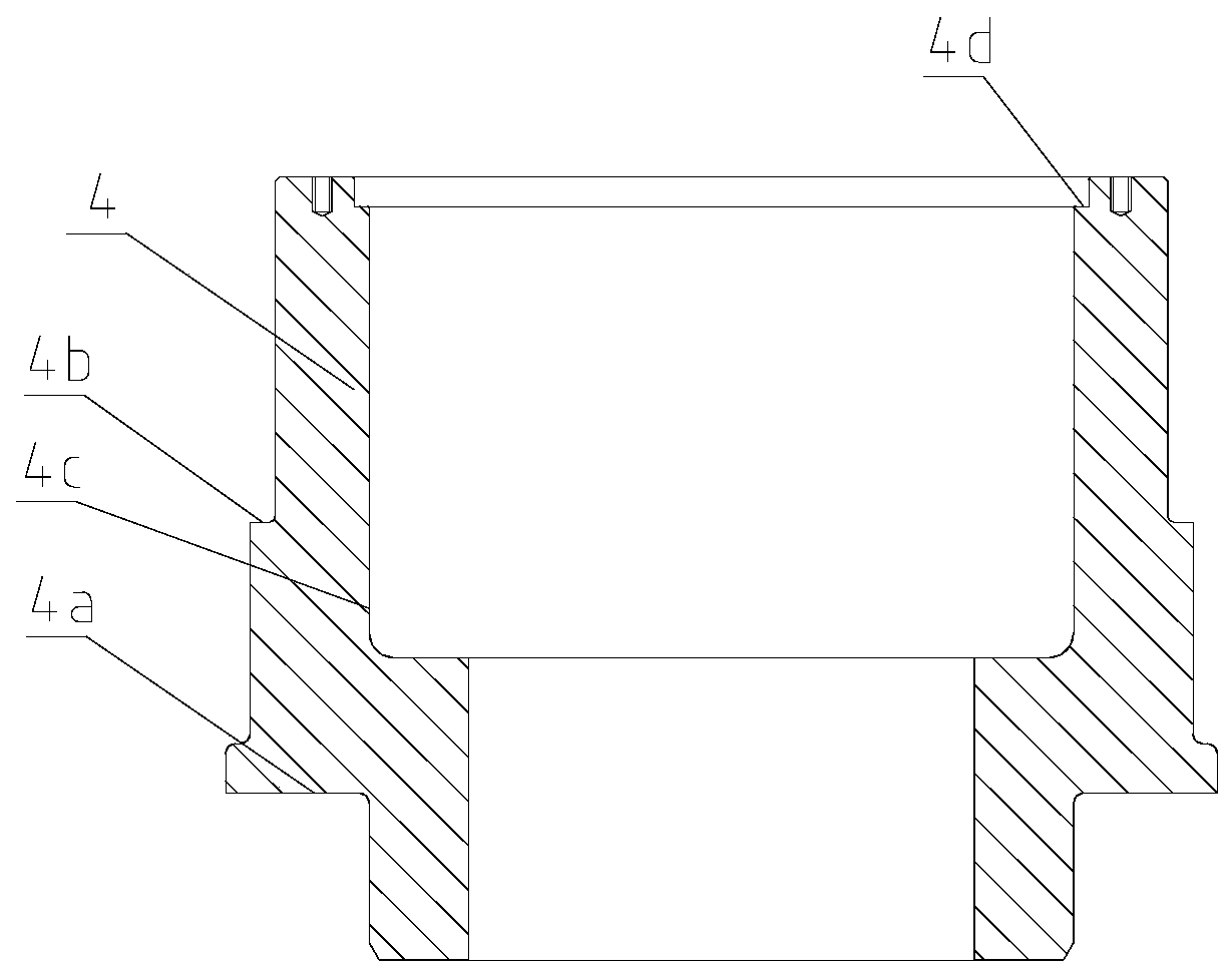
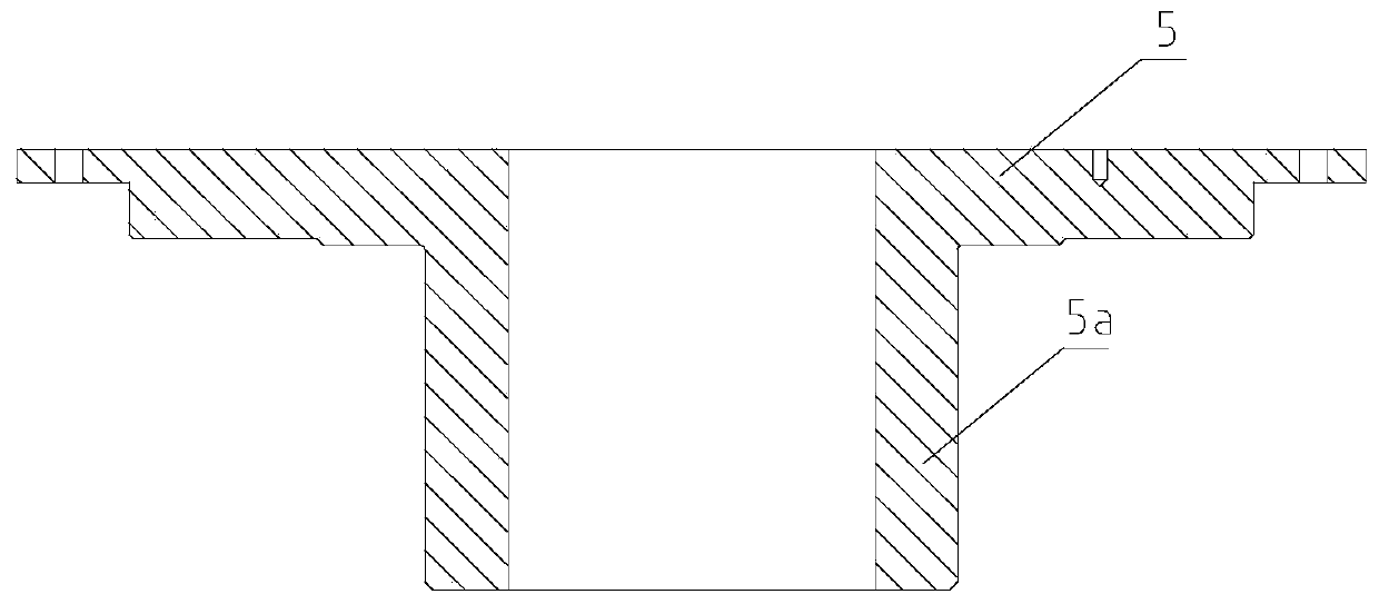
[0026] The embodiment of the present invention provides a supporting device, which is suitable for being installed between the lower panel a of the outer rotating column of the fixed column crane and the upper panel b of the inner fixed column, such as figure 1 As shown, the support device includes: a lower seat 1, a thrust spherical roller bearing 2, a spherical roller bearing 3, a first upper seat 4 and a second upper seat 5 fixedly connected with the lower panel a of the outer rotating column, and the lower seat 1 is provided with a first inner cavity 1a, the thrust spherical roller bearing 2 is located in the first inner cavity 1a, and the outer ring of the thrust spherical roller bearing 2 is installed on the bottom inner wall of the first inner cavity 1a, the first The upper seat 4 has a ring structure, and the first upper seat 4 is arranged in the first inner cavity 1 a and is arranged at a distance from the lower seat 1 . Such as figure 2 As shown, the outer wall of ...


PUM


Abstract

The invention discloses a supporting device, and belongs to the field of a machinery apparatus. The supporting device comprises a lower pedestal, a self-aligning thrust roller bearing, a self-aligningroller bearing, a first upper pedestal and a second upper pedestal. The lower pedestal is provided with a first inner chamber, in which the self-aligning thrust roller bearing is located; the outer ring of the self-aligning thrust roller bearing is installed at the inner wall of the bottom of the first inner chamber; the first upper pedestal is annular, is located in the first inner chamber, andis arranged relatively to the lower pedestal at an interval; the outer wall of the bottom of the first upper pedestal is provided with a first step front edge, the top surface of which is vertical toa central line of the first upper pedestal; an inner ring of the self-aligning thrust roller bearing is installed at the first step front edge, and an end of the inner ring of the self-aligning thrustroller bearing abuts against the top surface of the first step front edge. The supporting device can be applied to a fixed column crane that is light in weight and large in overturning moment and prevents the inner and outer rings of the self-aligning thrust roller bearing from being separated.

Description

technical field [0001] The invention relates to the field of mechanical devices, in particular to a supporting device. Background technique [0002] The fixed column crane is an important material lifting equipment on various ships, offshore platforms, and marine floating structures. It has the advantages of large lifting weight, high lifting height, small tail radius, and light weight. The fixed column crane includes a rotating part and a non-rotating part, the rotating part includes the outer rotating column, and the non-rotating part includes the inner fixed column. A supporting device is fixed between the lower panel of the outer rotating column and the upper panel of the inner fixed column. [0003] During the lifting process of the fixed column crane, the heavy object will generate an overturning moment on the rotating part of the fixed column crane, and the overturning moment acts indirectly on the supporting device in the form of horizontal force. In addition, the ...

Claims


Application Information

Patent Timeline
Patent Type & Authority Patents(China)
IPC IPC(8): B66C23/78B66C23/84F16C19/54
CPCB66C23/78B66C23/84F16C19/545
Inventor 邓祖学蔡智军罗鹏
Owner WUHAN MARINE MACHINERY PLANT
Why Eureka
Try Eureka