Open-end spinning device and spinning rotor for open-end spinning device

A technology of air spinning and rotor, which is applied in the direction of continuous winding spinning machines, spinning machines, textiles and papermaking, etc. It can solve the problems of high energy consumption and achieve the goals of reducing energy consumption, ensuring stability and saving materials. Effect

Active Publication Date: 2018-06-15
SAURER GERMANY GMBH & CO KG
View PDF8 Cites 1 Cited by
  • Summary
  • Abstract
  • Description
  • Claims
  • Application Information

AI Technical Summary

Problems solved by technology

As a result, they load the bearings and lead to higher energy consumption when accelerating to

Method used


Image

  • Open-end spinning device and spinning rotor for open-end spinning device
  • Open-end spinning device and spinning rotor for open-end spinning device
  • Open-end spinning device and spinning rotor for open-end spinning device

Examples


Embodiment Construction

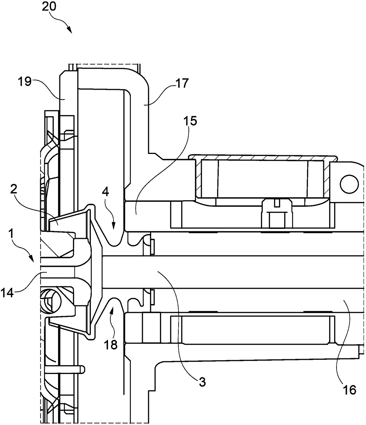
[0024] figure 1 Shown is an air spinning device 20 according to the invention. The spinning rotor 1 is rotatably installed in an air spinning device 20 . The spinning rotor 1 includes a rotor disk 2 and a rotor shaft 3 . Mounting of the rotor disk 2 on the rotor shaft 3 takes place by means of the flange 4 . The rotor disk 2 is arranged in a rotor housing 17 which can accept negative pressure. The rotor housing 17 is closed by a cover 19 which includes a channel plate connection. The channel plate connection projects into the interior 6 of the rotor disk 2 with the drawing channel 14 . Via the drawing channel 14 the yarn spun in the spinning rotor 1 is drawn off.

[0025] The rotor shaft 3 is mounted in bearings 16 outside the rotor housing 17 . The bearing 16 is held in a damping sleeve 15 protruding into the rotor housing 17 . One end of the damping sleeve 15 forms a through-opening 18 for the rotor housing 17 of the rotor shaft 3 for this purpose. Through hole 18 is...


PUM


Abstract

The present invention relates to an open-end spinning device and a spinning rotor (1) for the open-end spinning device (20). The spinning rotor comprises a rotor disk (2) and a rotor shaft (3). The rotor disk (3) has an annular wall section (11), a rotor base (8) and a collar (4). The collar (4) is connected to the rotor base (8) and has a bore (13) which accommodates the rotor shaft (3). According to the invention, the collar (4) has at least one annular web (21, 23) on its outer circumference, the outer diameter of which defines the outer diameter (D) of the collar (4), and the collar (4) has at least one circumferential depression (31, 32, 33, 34) for forming the at least one annular web (21,23).

Description

technical field [0001] The invention relates to an air spinning device and a spinning rotor for an air spinning device. Background technique [0002] DE 19910277 B4 discloses a spinning rotor for an air spinning device having a rotor disk with an annular wall forming the opening of the rotor and having a rotor base connected to the annular wall. The maximum outer diameter of the rotor disk is located in this connection area. A rotor groove is provided on the inner surface of the connecting portion, and the rotor disc has a flange (Bund) connected to the bottom of the rotor. The wall thickness of the annular wall portion increases from the rotor disk opening towards the connection portion. The thickness of the bottom of the rotor cup increases continuously from the groove of the rotor cup to the flange, and the wall thickness of the connecting part in the groove of the rotor cup is smaller than the minimum thickness of the bottom of the rotor cup and is between 0.3 mm and 1...

Claims


Application Information

Patent Timeline
IPC IPC(8): D01H4/10
CPCD01H4/10
Inventor 克劳迪娅·佳尔维茨L·温岑
Owner SAURER GERMANY GMBH & CO KG
Why Eureka
Try Eureka