Composite elevator cage and its producing method
A production method and composite technology, applied to elevators in buildings, transportation and packaging, etc., can solve the problems of easy wear, unsightly appearance, and high cost, and achieve strong wear resistance, high overall strength, and low production cost. Effect
Inactive Publication Date: 2010-12-01
忻建国 +1
View PDF0 Cites 0 Cited by
- Summary
- Abstract
- Description
- Claims
- Application Information
AI Technical Summary
Problems solved by technology
Cast iron sills have high strength, good wear resistance, and strong pressure bearing capacity, but are prone to rust and are not beautiful, and are generally only used on freight elevators; while aluminum alloy sills are beautiful in appearance and rust-free, but weak in strength and easy to wear, And the cost is high, so it is usually used on passenger elevators
Method used
View moreImage
Smart ImageViewing Examples

Examples
Embodiment 1
Embodiment 2
Embodiment 3
Login to View More PUM
 Abstract
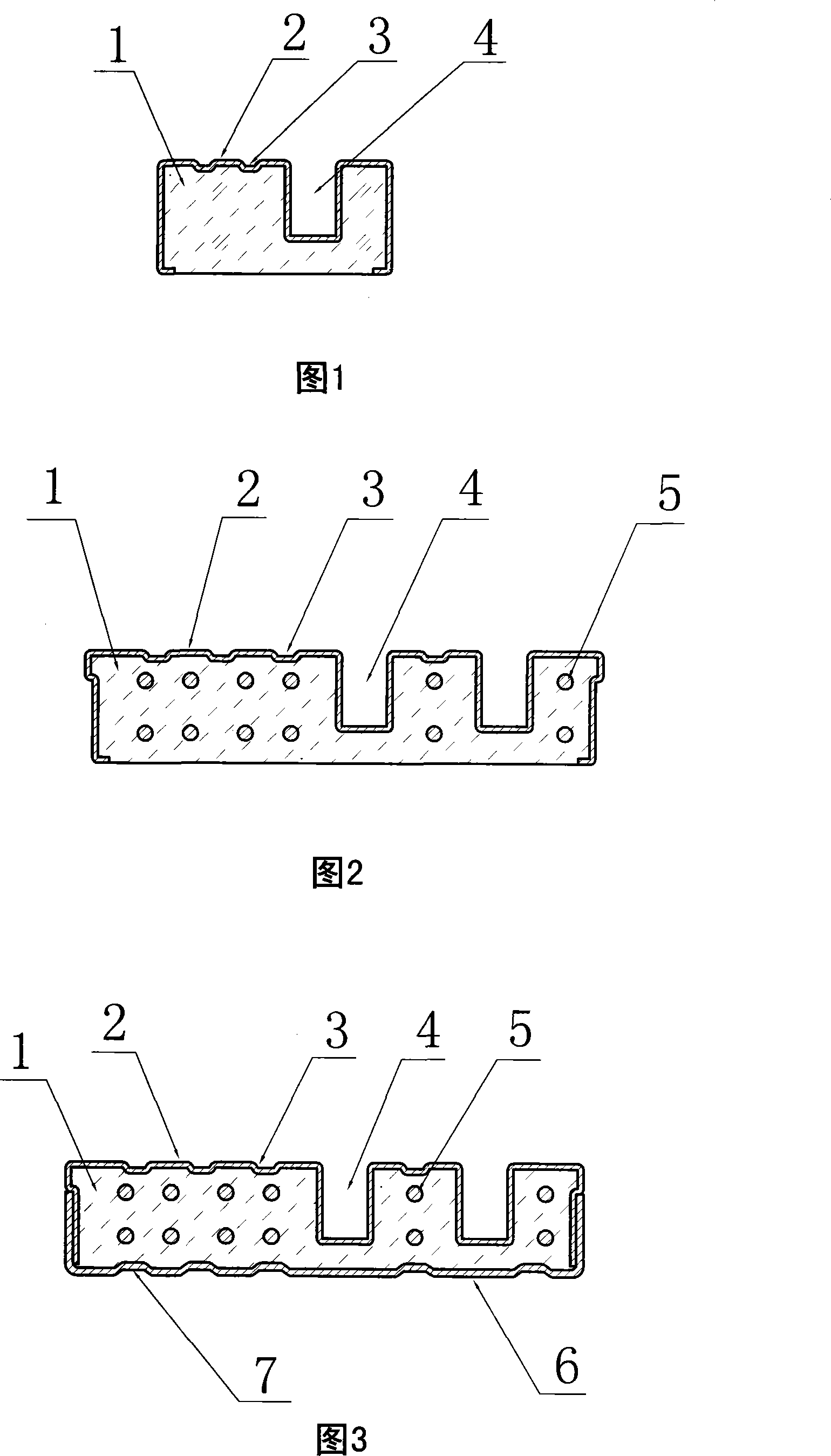
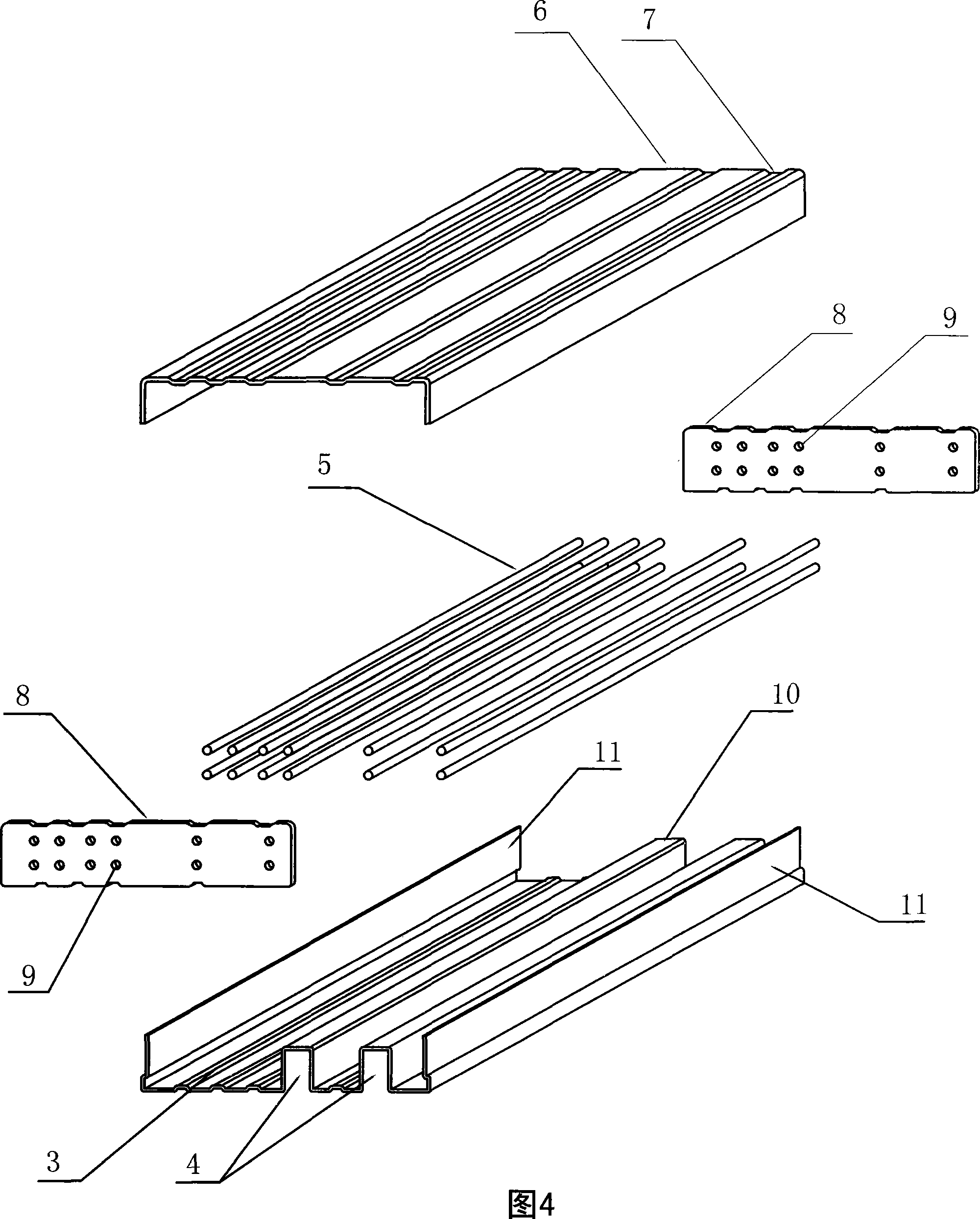
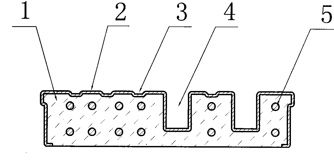
The invention relates to a compound elevator sill and the manufacturing method, and the product comprises a basal body and the protecting layer plate wrapped outside the basal body. The basal body is made of concrete or armoured concrete, the protecting plate wrapped the basal body is provided with at least the upper plate made of stainless steel. The manufacturing method is that the moulding groove shaped protecting layer plate is inversely positioned on the shaking rack, the concrete is poured into the groove cavity, then the shaking machine is started to make the concrete in the groove cavity shaking firm and flat, at last, the product is formed by static positioning natural maintenance or steam maintenance. The product of the invention has the advantages of beautiful appearance without rusting, strong wearlessness, and high integrated intensity which is of pressure-resisting. The basal body is the cheap armoured concrete with low production cost, thereby satisfying the comprehensive requirement for the passenger, goods ladder. The compound elevator sill has simple and proper manufacturing method, and the quality of the shaped product is stable and reliable.
Description
Composite elevator sill and production method thereof technical field The invention relates to a sill of an elevator car door or a landing door of an elevator shaft, in particular to a composite sill made of different materials and a production method thereof. Background technique The car door in the existing elevator installation or the sill of the hoistway landing door are mostly made of cast iron or aluminum alloy single material. Cast iron sills have high strength, good wear resistance, and strong pressure bearing capacity, but are prone to rust and are not beautiful, and are generally only used on freight elevators; while aluminum alloy sills are beautiful in appearance and rust-free, but weak in strength and easy to wear, And the cost is high, so it is usually used on passenger elevators. Contents of the invention The purpose of the present invention is to provide a composite elevator sill with high strength, good wear resistance, beautiful surface, no rust, low ...
Claims
Login to View More Application Information
Patent Timeline
 Patent Type & Authority Patents(China)
IPC IPC(8): B66B13/00
Inventor 忻建国陈惠琪
Owner 忻建国
Features
- R&D
- Intellectual Property
- Life Sciences
- Materials
- Tech Scout
- Unparalleled Data Quality
- Higher Quality Content
- 60% Fewer Hallucinations
Learn More Browse by: Latest US Patents, China's latest patents, Technical Efficacy Thesaurus, Application Domain, Technology Topic, Popular Technical Reports.
© 2025 PatSnap. All rights reserved.Legal|Privacy policy|Modern Slavery Act Transparency Statement|Sitemap|About US| Contact US: help@patsnap.com