Folding combined type temporary bridge device

A combination and bridge technology, applied to bridges, bridge parts, bridge forms, etc., can solve problems such as poor versatility and complex structure, and achieve the effects of easy transportation, good structural strength, and good stability

Active Publication Date: 2018-06-15
SICHUAN COLLEGE OF ARCHITECTURAL TECH
View PDF5 Cites 4 Cited by
  • Summary
  • Abstract
  • Description
  • Claims
  • Application Information

AI Technical Summary

Problems solved by technology

[0004] Aiming at the problems of complex structure and poor versatility in the above-mentioned prior art, the present invention provides a foldable and combined temporary bridge device that is not attached to a special means of transportation and has a simple structure that can be quickly disassembled and assembled for easy transportation.

Method used


Image

  • Folding combined type temporary bridge device
  • Folding combined type temporary bridge device
  • Folding combined type temporary bridge device

Examples


Embodiment 1

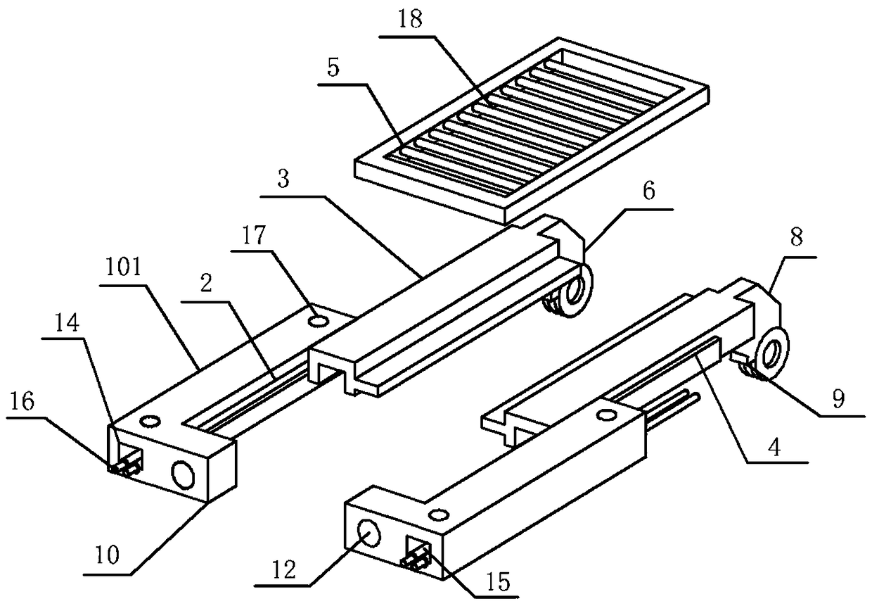
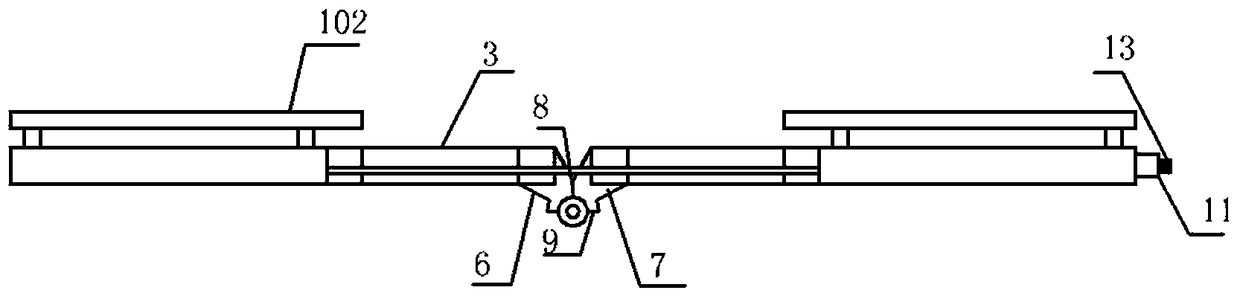
[0025] A kind of foldable and combined temporary bridge device of the present embodiment, such as figure 1 , figure 2 , image 3 with Figure 4 As shown, at least two folded bridge assemblies are included, and a whole bridge structure is formed by splicing the folded bridge assemblies with each other. Frame 101 and the fixed plate 102 structure that is arranged on the bottom frame 101; The bottom frame 101 comprises two mutually parallel square steel structures and two mutually parallel channel steels 3, and each square steel structure inside is provided with A slide rail 2 parallel to the long side of the square; the channel steel 3 is slidingly connected with the square steel through a T-shaped convex strip 4 that is arranged on one side and embedded in the slide rail 2; The fixed plate 102 is parallel to the mesh plate 5; the two groups of channel steel 3 on two adjacent folded plates 1 are hinged so that the two folded plates 1 can be rotated by 90° for folding.

Embodiment 2

[0027] This embodiment is further defined on the basis of the above-mentioned embodiments, the channel steel 3 is provided with an ear seat 6 at the hinged end, and the channel steel 3 corresponding to the adjacent folded plate 1 is provided with a hinge joint with the ear seat 6. The single-ear insert 7 is inserted into the corresponding ear seat 6 and inserted into the rotating shaft to form a hinged relationship; the ear seat 6 and the single-ear insert 7 are provided with two foldable parts for limiting mutual hinge The parallel flange 8 that continues to rotate upward when the plate 1 is completely opened horizontally, and the ear seat 6 and the single ear plug 7 are also provided with a semicircle that is used to limit the two hinged folding plates 1 to continue to rotate toward each other when they are fully parallel folded flange9. Other parts of this embodiment are the same as those of the foregoing embodiment, and will not be repeated here.

Embodiment 3

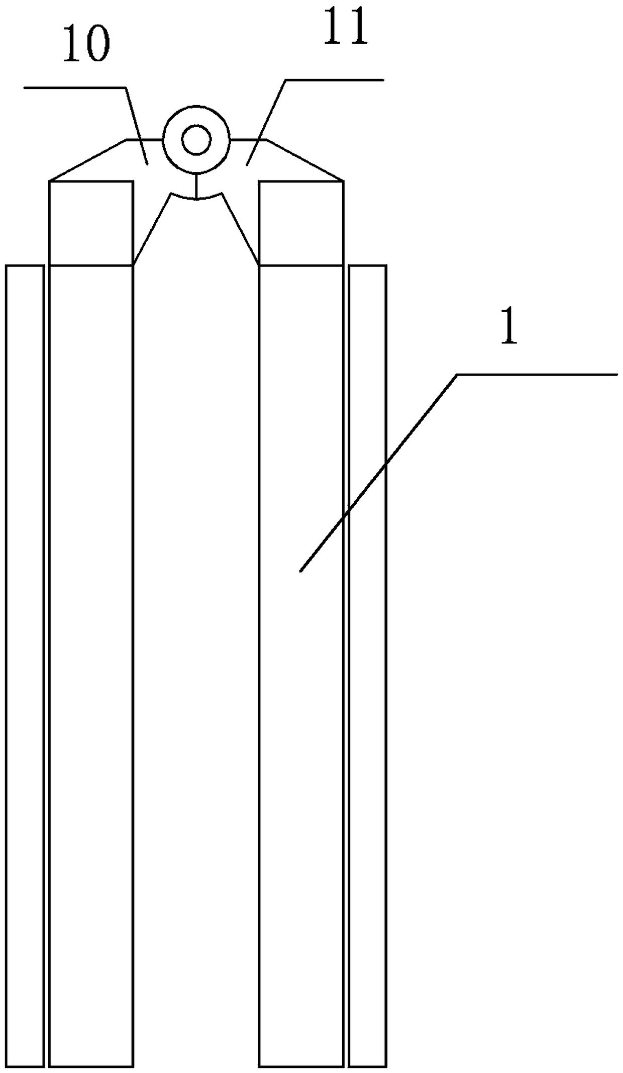
[0029] This embodiment is further defined on the basis of the above embodiments, the square steel is an L-shaped structure, the side of the square steel on the same folded bridge assembly away from the hinge is provided with an insert perpendicular to the long side of the square steel The socket 10, on the other side of the same folding bridge assembly and also away from the direction steel end of the hinged end, is provided with a socket block 11 that is mated with the socket block 10, and the end surface of the socket 10 is provided with Perpendicular to the round through hole 12 on the end surface, the plug block 11 is provided with a screw rod 13 inserted into and passed through the corresponding round through hole 12 and a nut is provided at the end to cooperate and fix it. Other parts of this embodiment are the same as those of the foregoing embodiment, and will not be repeated here.


PUM


Abstract

The invention discloses a folding combined type temporary bridge device. The folding combined type temporary bridge device comprises at least two folding bridge assemblies; the folding bridge assemblies are spliced with each other to form an integral bridge structure; each folding bridge assembly comprises two hinged folding plates; each folding plate comprises underframes and fixed plate structures, wherein the underframes are connected with each other in a telescopic manner and the fixed plate structures are arranged on the underframes; each underframe comprises two square steel structures and two parallel steel channels, wherein the two square steel structures are arranged in parallel; a slide rail parallel to the long side of the square steel is arranged on the internal side of each square steel structure; the steel channels are connected with the square steels in a sliding manner by using T-shaped convex strips which are arranged on one side and embedded into the slide rails; a net plate parallel to the fixed plate are arranged between each two channel steels; the two groups of steel channels on the two adjacent folding plates are hinged with each other so that the two foldingplates can rotate 90 degrees to be folded. The folding combined type temporary bridge device has the advantages that the structure is simple and compact; an effect that the storage, folding and transporting are convenient by splicing the multiple folding bridge assemblies is achieved.

Description

technical field [0001] The invention relates to the field of bridge equipment, in particular to a folding and combined temporary bridge device. Background technique [0002] Bridges generally refer to structures erected on rivers, lakes and seas to allow vehicles and pedestrians to pass smoothly. In order to adapt to the modern high-speed development of the transportation industry, bridges are also extended to buildings that cross mountain streams, poor geology or meet other transportation needs to make traffic more convenient. A bridge is generally composed of a superstructure, a substructure, a support and ancillary structures. The superstructure is also called a bridge span structure, which is the main structure for crossing obstacles; the substructure includes abutments, piers and foundations; Or the force transmission device installed at the supporting place of the bridge abutment; the auxiliary structures refer to the bridge head board, conical slope protection, bank ...

Claims


Application Information

Patent Timeline
Patent Type & Authority Applications(China)
IPC IPC(8): E01D15/10E01D19/00
CPCE01D15/10E01D19/00
Inventor 王奕骁王旭东
Owner SICHUAN COLLEGE OF ARCHITECTURAL TECH
Why Eureka
Try Eureka