Arrangement structure for heater for Stirling engine and mounting method

A technology of Stirling engine and layout structure, which is applied in the direction of hot gas variable capacity engine device, machine/engine, mechanical equipment, etc. Coarse, material performance decline and other problems, to ensure the performance of anti-fatigue materials, compact layout, and ensure the effect of working performance

Active Publication Date: 2018-06-15
SHANGHAI MICROPOWERS
View PDF5 Cites 3 Cited by
  • Summary
  • Abstract
  • Description
  • Claims
  • Application Information

AI Technical Summary

Problems solved by technology

Because the external dimension of the heating tube on the heater cylinder exceeds the inner diameter of the flange, if the flange and the heater cylinder are separated, when brazing the heating tube, the flange and the heater cylinder must be placed together. In the brazing furnace, this process will make the flange structure grain coarse due to the synergistic effect of brazing and heat treatment, which reduces the original fatigue resistance of the material; and if the flange and the cylinder are integrated , due to the need to enter the brazing furnace, the flange will also have the phenomenon of material performance degradation
The decline in material performance will lead to cracks, fractures and other failures when the flange is working under high temperature and high pressure due to high cycle fatigue and large loads, which seriously affects the reliability of the engine.
[0004] In order to solve the above problems, the split flange is improved in the industry, and the integral flange is split into two halves, so that the brazing furnace can not be carried out together with the heater cylinder, but the center coincidence degree is easy to be caused by the split flange installation Not good, it affects the service strength of the flange, and also causes fatigue damage caused by uneven force on the bonding surface of the heater cylinder

Method used


Image

  • Arrangement structure for heater for Stirling engine and mounting method
  • Arrangement structure for heater for Stirling engine and mounting method
  • Arrangement structure for heater for Stirling engine and mounting method

Examples


Embodiment Construction

[0059] In order to more clearly illustrate the embodiments of the present invention or the technical solutions in the prior art, the specific implementation manners of the present invention will be described below with reference to the accompanying drawings. Obviously, the accompanying drawings in the following description are only some embodiments of the present invention, and those skilled in the art can obtain other accompanying drawings based on these drawings and obtain other implementations.

[0060] In order to make the drawing concise, the parts related to the present invention are only schematically shown in each drawing, and they do not represent the actual structure of the product. In addition, to make the drawings concise and easy to understand, in some drawings, only one of the components having the same structure or function is schematically shown, or only one of them is marked. Herein, "a" not only means "only one", but also means "more than one". In this arti...


PUM


Abstract

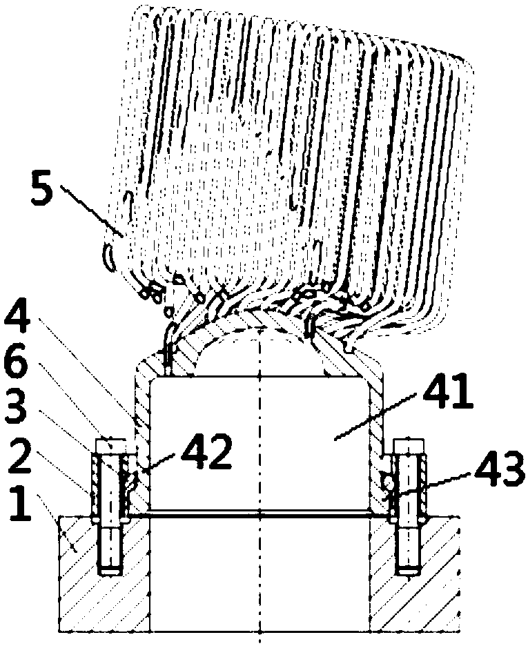
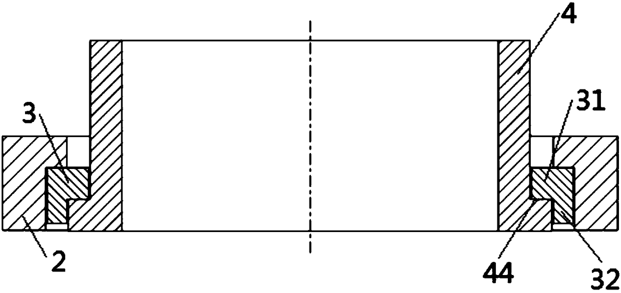
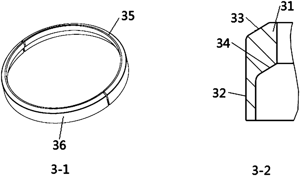
The invention discloses an arrangement structure for a heater for a Stirling engine and a mounting method. The arrangement structure comprises an engine body, a flange, a transition ring and the heater. The transition ring is formed by splicing the at least two sub transition rings; the heater comprises a mounting end and a heating end, and the heating end is provided with heating pipes; and the outer side of the mounting end is sleeved with the flange and the transition ring, so that the flange mounts the heater on the machine body through the transition ring. The flange can mount the heateron the machine body after the heater is welded to the heating pipes, accordingly, working properties such as strength, fatigue resistance and anti-loading capacity of the flange are guaranteed, faultsof cracks, factures and the like which occur in the using process of the flange are avoided effectively, and the working reliability of the Stirling engine is guaranteed.

Description

technical field [0001] The invention relates to the technical field of a Stirling engine, and relates to an arrangement structure and an installation method of a heater for a Stirling engine. Background technique [0002] Stirling Engine is a closed regenerative cycle engine heated by external energy. It has the characteristics of high efficiency, low noise, low pollution and strong energy adaptability. The heater is an important part of the Stirling engine, which is fixedly connected to the fuselage through a flange structure or other structural forms. If the flange connection structure is adopted, the installation method and reliability of the flange structure have an important influence on the performance of the Stirling engine. [0003] Currently, if Figure 4 with Figure 5 As shown, the Stirling engine heater flange structure is generally connected by the heater cylinder and the flange through plane contact, and the flange is fixedly connected with the fuselage by sc...

Claims


Application Information

Patent Timeline
Patent Type & Authority Applications(China)
IPC IPC(8): F02G1/055
CPCF02G1/055
Inventor 孙绪聪朱辰元黄晓宇周建明顾根香
Owner SHANGHAI MICROPOWERS
Why Eureka
Try Eureka