
Anti-light-loading-skidding square and round pocket holder
A cage and pocket technology, used in bearings, bearing components, bearings in rotating motion, etc., can solve problems such as easy slippage, impact on bearing life and reliability, bearing failure, etc., to reduce weight, ensure strength, improve The effect of carrying capacity
- Summary
- Abstract
- Description
- Claims
- Application Information
AI Technical Summary
Problems solved by technology
Method used
Image


Examples
specific Embodiment approach 1
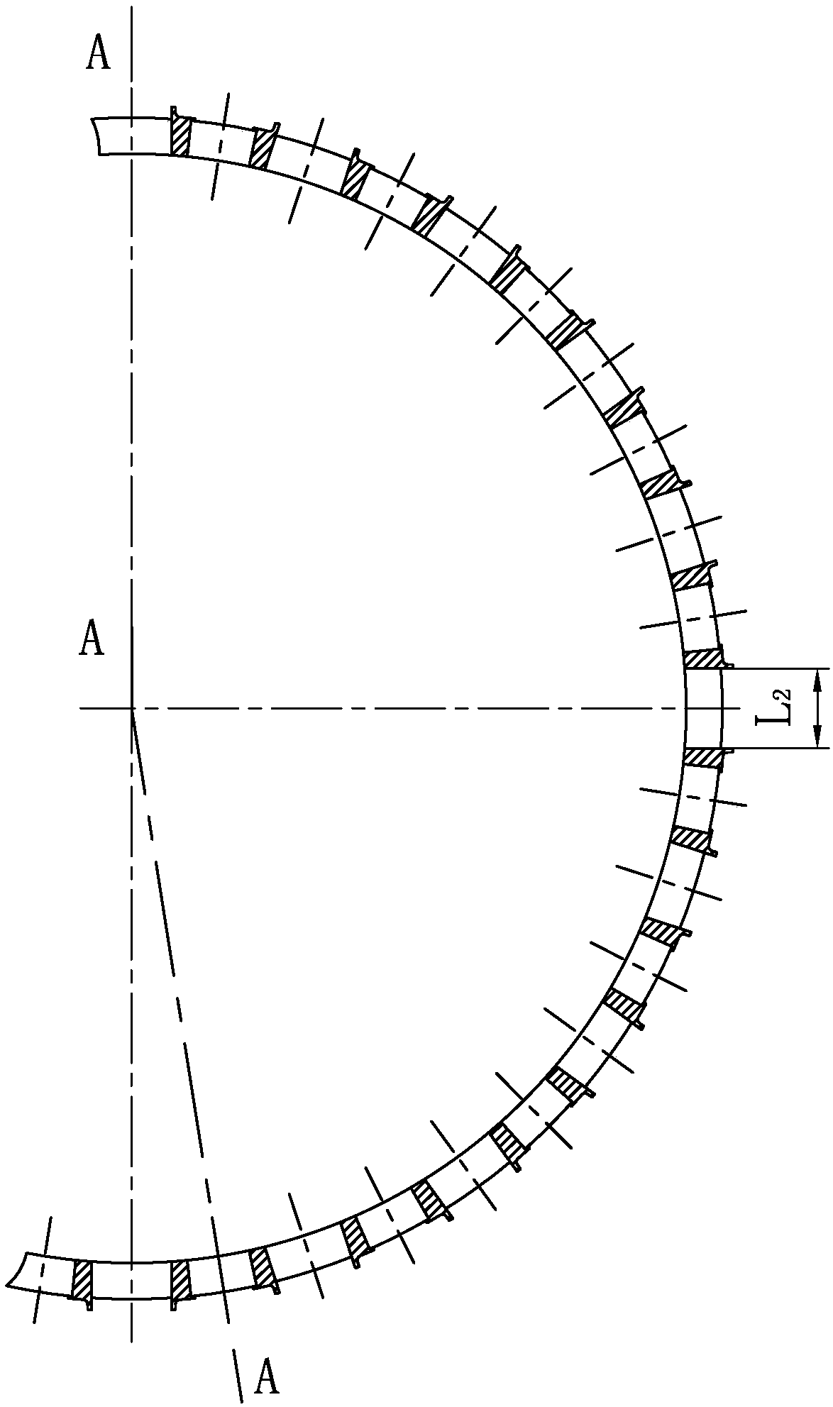
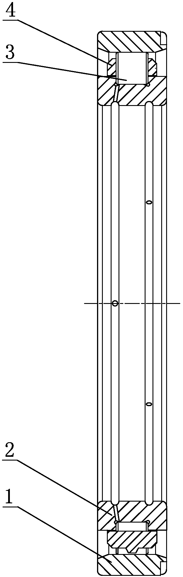
[0019] Specific implementation mode one: combine figure 1 and image 3 Describe this embodiment, an anti-light-load slipping square pocket cage of this embodiment, which includes an outer ring 1, an inner ring 2, cylindrical rollers 3 and a cage 4, the outer ring 1 and the inner ring 2 There is a cage 4 between them, and the cage 4 is an annular cage, and a plurality of square pockets 4-1 are evenly opened on the circumference of the annular cage, and the cylindrical roller 3 is installed in the square pocket 4 of the cage 4 -1, a circular pocket 4-2 is opened between two adjacent square pockets 4-1 of the cage 4, and the number of square pockets 4-1 of the cage 4 is equal to the circle of the cage 4. The quantity of shape pocket 4-2 is equal.
specific Embodiment approach 2
[0020] Specific implementation mode two: combination figure 1 and figure 2 Describe this embodiment, the square pockets 4 - 1 of this embodiment are evenly and symmetrically distributed on the cage 4 . In this way, the square pocket 4-1 is used for positioning and isolating the cylindrical rollers 3 to prevent the inclination of the cylindrical rollers 3 or friction between the cylindrical rollers 3, effectively preventing the increase of the rotational torque. Other compositions and connections are the same as in the first embodiment.
specific Embodiment approach 3
[0021] Specific implementation mode three: combination figure 1 and figure 2 To describe this embodiment, the circular pockets 4 - 2 of this embodiment are evenly and symmetrically distributed on the cage 4 . In this way, the circular pockets 4-2 are evenly and symmetrically distributed on the cage 4, which is conducive to maintaining the dynamic balance of the cylindrical roller bearing and improving the load-carrying capacity of a single roller. Other compositions and connections are the same as those in Embodiment 1 or Embodiment 2.
PUM
 Abstract
Description
Claims
Application Information