Exhaust superheat degree control method of refrigerating and heat pump unit
A technology of exhaust superheat and heat pump units, which is applied in the direction of refrigerators, refrigeration components, refrigeration safety arrangements, etc., can solve the problems of high cost and expensive pressure sensors, and achieve the effect of reducing control costs and ensuring safe operation
- Summary
- Abstract
- Description
- Claims
- Application Information
AI Technical Summary
Problems solved by technology
Method used
Image

Examples
Embodiment 1
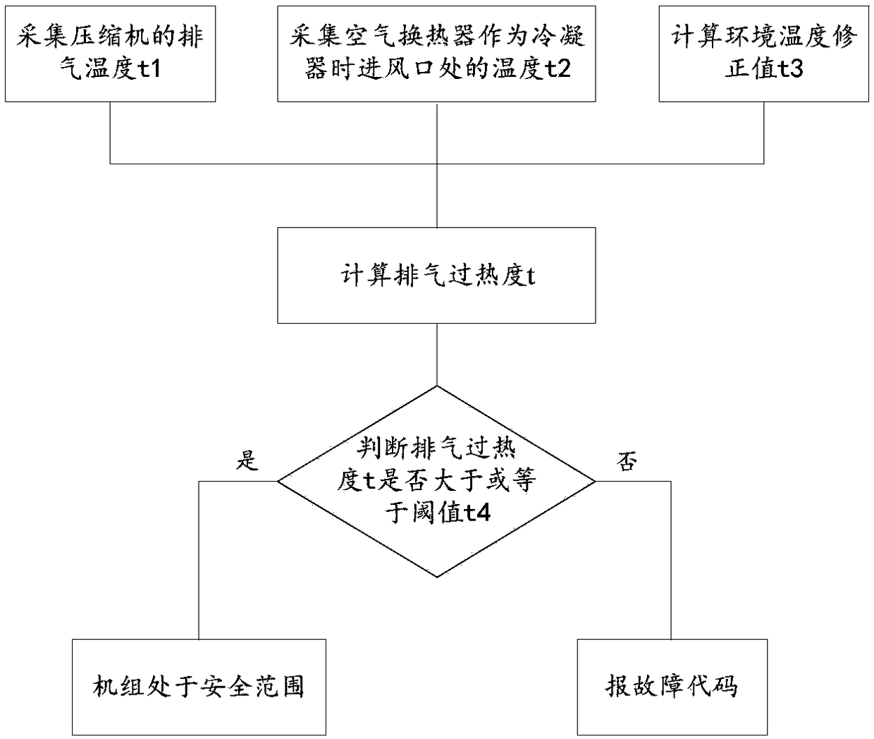
[0045] Such as figure 1 As shown, this embodiment 1 describes a method for controlling the exhaust superheat degree in refrigeration and heat pump units, which is applicable to the situation where there are two air heat exchangers in refrigeration and heat pump units, such as Figure 4 shown.
[0046] A method for controlling the degree of exhaust superheat in a refrigeration and heat pump unit, comprising the following steps:
[0047] s11. Use the discharge temperature sensor 2 to collect the discharge temperature t1 of the compressor 1 .
[0048] Wherein, the exhaust gas temperature sensor 2 is set at a position 50-300 mm away from the compressor exhaust port, for example, 50 mm, 100 mm, 150 mm, 200 mm, 250 mm and so on.
[0049] s12. Use the ambient temperature sensor 3 to measure the temperature t2 at the air inlet when one of the air heat exchangers 5 is used as a condenser. Wherein, the ambient temperature sensor 3 is arranged at the air inlet of the air heat exchange...
Embodiment 2
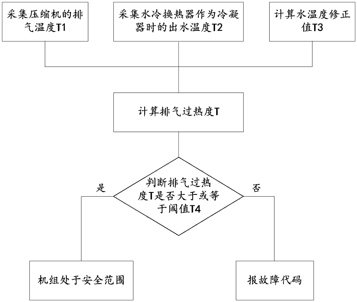
[0064] Such as figure 2 As shown, this embodiment 2 also describes a method for controlling the exhaust superheat in refrigeration and heat pump units. This method is applicable to the situation where there are two water-cooled heat exchangers in refrigeration and heat pump units, such Figure 5 shown.
[0065] A method for controlling the degree of exhaust superheat in a refrigeration and heat pump unit, comprising the following steps:
[0066] s21. Use the exhaust temperature sensor to collect the exhaust temperature T1 of the compressor 1 .
[0067] Wherein, the exhaust gas temperature sensor 2 is set at a position 50-300 mm away from the compressor exhaust port, for example, 50 mm, 100 mm, 150 mm, 200 mm, 250 mm and so on.
[0068] s22. Using the cooling outlet water temperature sensor 4 to measure the outlet water temperature T2 when one of the water-cooled heat exchangers 6 is used as a condenser.
[0069] Wherein, the cooling outlet water temperature sensor is arran...
Embodiment 3
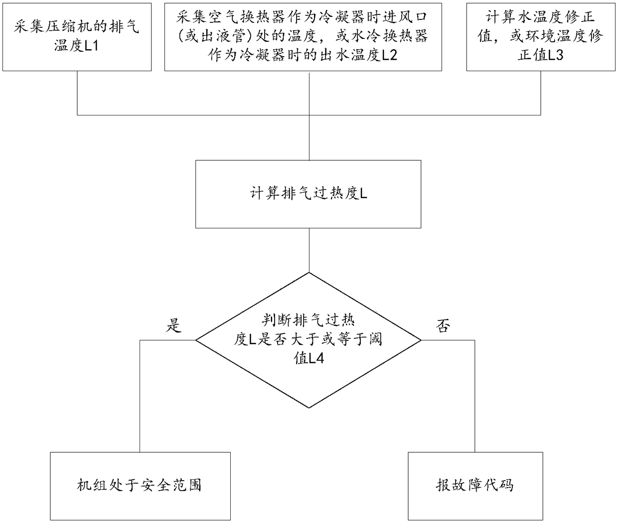
[0077] Such as image 3 As shown, this embodiment 3 also describes a method for controlling the degree of superheat of the exhaust gas in the refrigeration and heat pump unit, which is applicable to the situation where there is a water-cooled heat exchanger and an air heat exchanger in the refrigeration and heat pump unit, such as Figure 6 shown.
[0078] The exhaust superheat control method in this embodiment 3 has two situations:
[0079] The first is that the air heat exchanger 5 is used as a condenser, and the water-cooled heat exchanger 6 is used as an evaporator; the second is that the water-cooled heat exchanger 6 is used as a condenser, and the air heat exchanger 5 is used as an evaporator. in:
[0080] The exhaust superheat control method in the first case is carried out according to the following steps:
[0081] s31. Use the discharge temperature sensor 2 to collect the discharge temperature L1 of the compressor.
[0082] Wherein, the exhaust gas temperature sen...
PUM
| Property | Measurement | Unit |
|---|---|---|
| Heat transfer area | aaaaa | aaaaa |
Abstract
Description
Claims
Application Information
 - Generate Ideas
- Intellectual Property
- Life Sciences
- Materials
- Tech Scout
- Unparalleled Data Quality
- Higher Quality Content
- 60% Fewer Hallucinations
Browse by: Latest US Patents, China's latest patents, Technical Efficacy Thesaurus, Application Domain, Technology Topic, Popular Technical Reports.
© 2025 PatSnap. All rights reserved.Legal|Privacy policy|Modern Slavery Act Transparency Statement|Sitemap|About US| Contact US: help@patsnap.com