
Indoor positioning system based on distributed antenna and method thereof

A distributed antenna and indoor positioning technology, which is applied to measuring devices, instruments, surveying and navigation, etc., can solve the problems of inaccurate positioning, cumbersome positioning estimation process, and poor real-time performance, so as to improve the receiving power of useful signals and effectively resist indoor Multipath effect, effect of increasing coverage space

Active Publication Date: 2018-06-15
西安茂德通讯科技有限公司
View PDF13 Cites 10 Cited by
  • Summary
  • Abstract
  • Description
  • Claims
  • Application Information

AI Technical Summary

Problems solved by technology

[0003] The Chinese patent with the application number 201410831889.8 uses the 3D information collected by the sensor for indoor environment modeling, position analysis and information calibration. The user collects the current scene information, and realizes the user's indoor positioning by comparing and feature matching with the 3D environment model information. , this method needs to establish an accurate three-dimensional environment model, and the positioning estimation process is cumbersome; the Chinese patent application number 201610813895. Point is the coordinate origin to establish a platform coordinate system; introduce a laser 3D scanner at the reference point to obtain indoor 3D point cloud information, and unify the point cloud into the platform coordinate system; further coordinate conversion between the ultra-wideband indoor positioning system coordinate system and the above coordinate data , to complete indoor target positioning, but the positioning system has a complex structure, high cost, and difficult implementation
[0004] None of the above methods are suitable for complex environments, and have the disadvantages of imprecise positioning and poor real-time performance

Method used


Image

  • Indoor positioning system based on distributed antenna and method thereof
  • Indoor positioning system based on distributed antenna and method thereof
  • Indoor positioning system based on distributed antenna and method thereof

Examples


Embodiment Construction

[0052] The present invention will be described in detail below in conjunction with the accompanying drawings and embodiments.

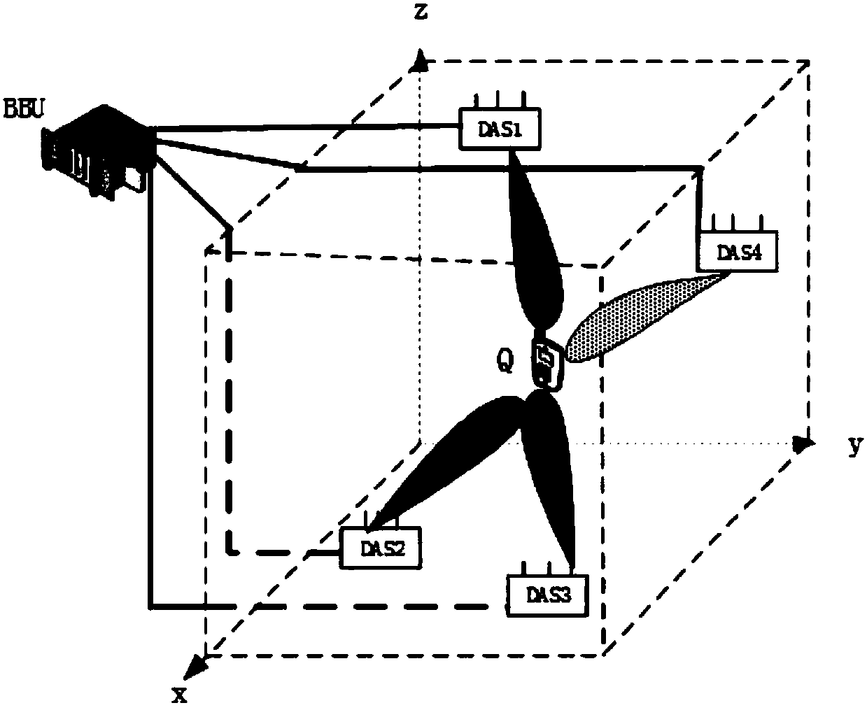
[0053] refer to figure 1 , an indoor positioning system based on a distributed antenna group, including a base station of a baseband processing unit BBU (Building Base band Unite) and a DAS 1 、DAS 2 、DAS 3 and DAS 4 The antenna group DAS (Distributed Antenna Sets) composed of four antenna groups, the baseband processing unit BBU (Building Base band Unite) and the indoor antenna group DAS through the feeder k Antenna connection in the antenna group DAS k Receiving the sounding signal sent by the terminal Q respectively, the baseband processing unit BBU passes the distributed antenna group DAS k After receiving the sounding signal sent by the terminal Q, perform corresponding processing;

[0054] The antenna group DAS k (k=1,2,...,4) all use planar arrays, the number of array elements is M k ×N k ,M k is the number of rows of the planar antenn...


PUM


Abstract

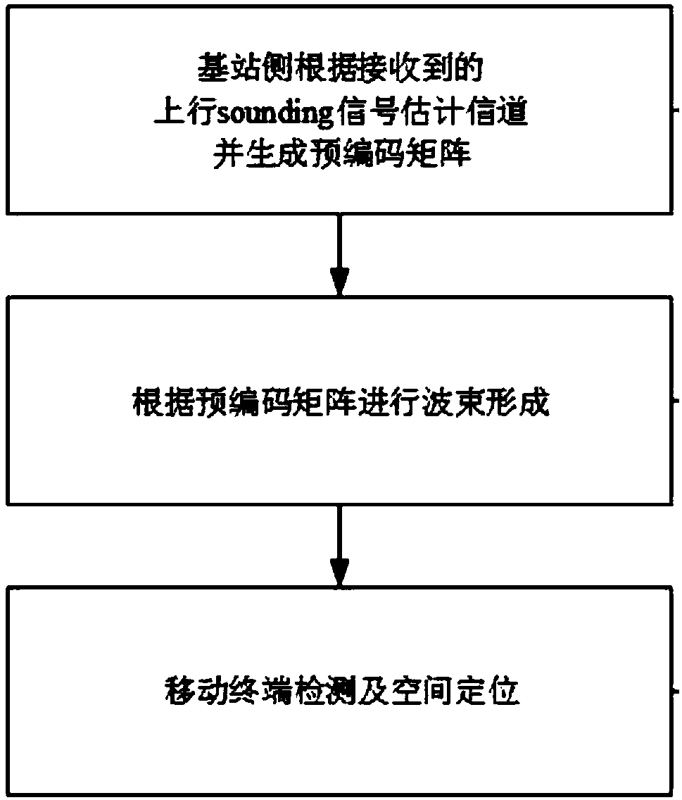
The invention relates to a wireless indoor positioning system based on a distributed antenna and a method thereof. The system contains a base station, an antenna and a terminal, the base station is connected with each indoor antenna through a feed wire, the antenna set is respectively receives a sounding signal transmitted by a terminal, after the base station obtains the signal sent by the terminal through the antenna, corresponding processing is carried out, and the antenna set employs a plane array; the method is characterized in that a channel is estimated by the base station according tothe received uplink sounding signal and a precoding matrix is generated; wave beam formation is realized according to a precoding matrix, and finally terminal detection and space positioning are carried out. The system uses the distributed antenna and combines with three-dimensional intelligent wave beam, realizes indoor real-time space positioning, is suitable for complex environment, and has theadvantages of accurate positioning and good real-time performance.

Description

technical field [0001] The present invention relates to the technical field of space positioning, in particular to an indoor positioning system and method based on distributed antennas. Background technique [0002] With the rapid increase of data services and multimedia services, people's demand for positioning is increasing. Especially in complex indoor environments, such as airport halls, supermarkets, libraries, underground parking lots, etc., it is often necessary to determine the mobile terminal or its Indoor location information of holders, facilities and objects. Most of the current positioning methods are researched on two-dimensional planes. However, in practical applications, it is often necessary to provide three-dimensional position information of nodes. Indoor three-dimensional positioning technology has greater practical value than two-dimensional plane positioning. Due to the particularity and complexity of the indoor environment, the indoor three-dimensiona...

Claims


Application Information

Patent Timeline
IPC IPC(8): G01C21/20
CPCG01C21/206
Inventor 王衍文王渭森任义烽王世芳马玥
Owner 西安茂德通讯科技有限公司
Learn More