High impact inertia micro-fluid power connection switch and manufacturing method thereof

A manufacturing method and microfluidic technology, applied in the direction of electric switches, circuits, electrical components, etc., can solve the problems of closure, unfavorable fuze safety, etc., and achieve the effect of large contact area, simple structure, and simple processing method

Active Publication Date: 2018-06-15
NANJING UNIV OF SCI & TECH
View PDF8 Cites 11 Cited by
  • Summary
  • Abstract
  • Description
  • Claims
  • Application Information

AI Technical Summary

Problems solved by technology

However, in the case of an accidental fall of the fuze, the sw...

Method used


Image

  • High impact inertia micro-fluid power connection switch and manufacturing method thereof
  • High impact inertia micro-fluid power connection switch and manufacturing method thereof
  • High impact inertia micro-fluid power connection switch and manufacturing method thereof

Examples


Embodiment Construction

[0031] In order to illustrate the technical scheme and technical purpose of the present invention, the present invention will be further introduced below in conjunction with the accompanying drawings and specific embodiments.

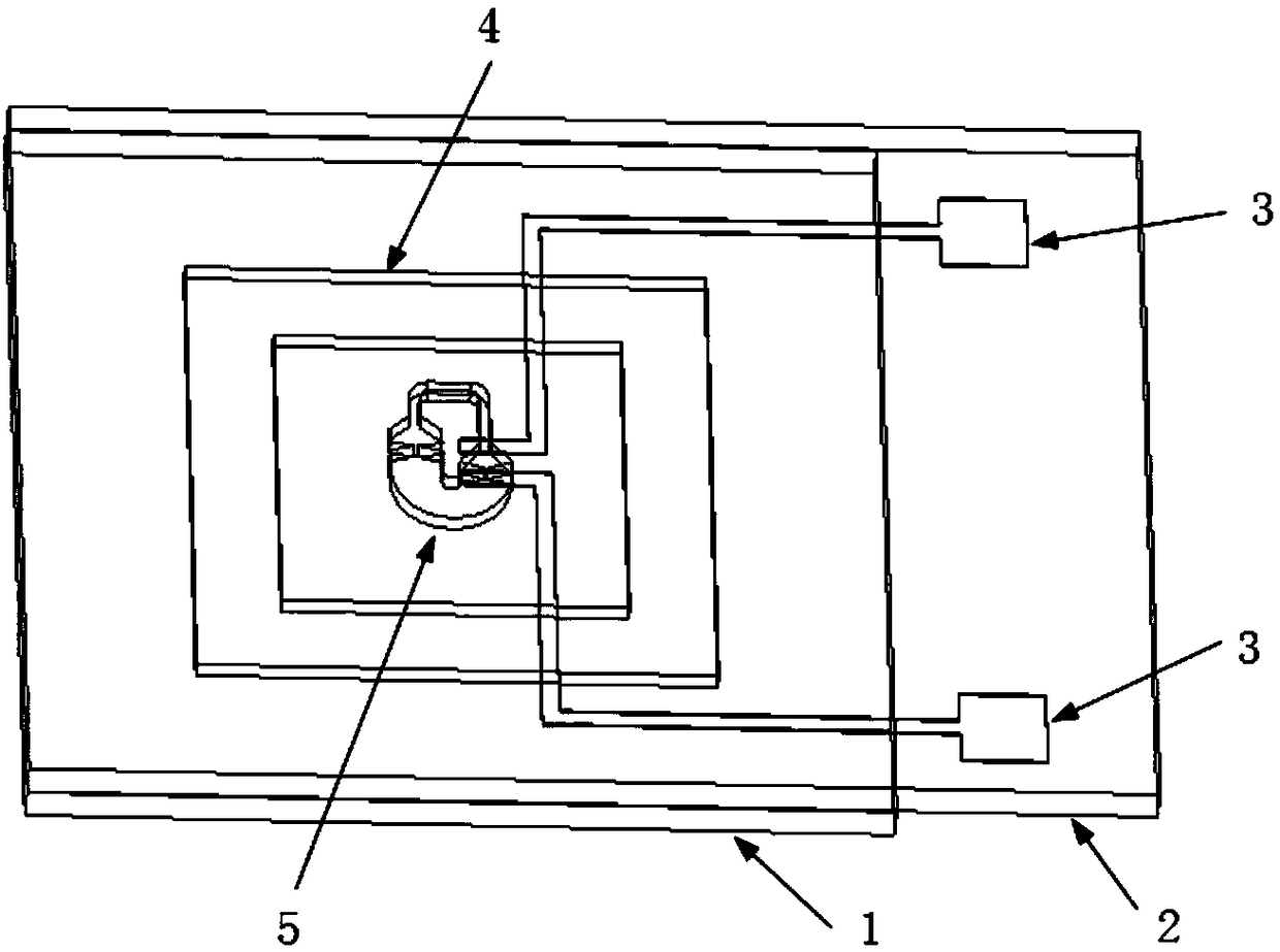
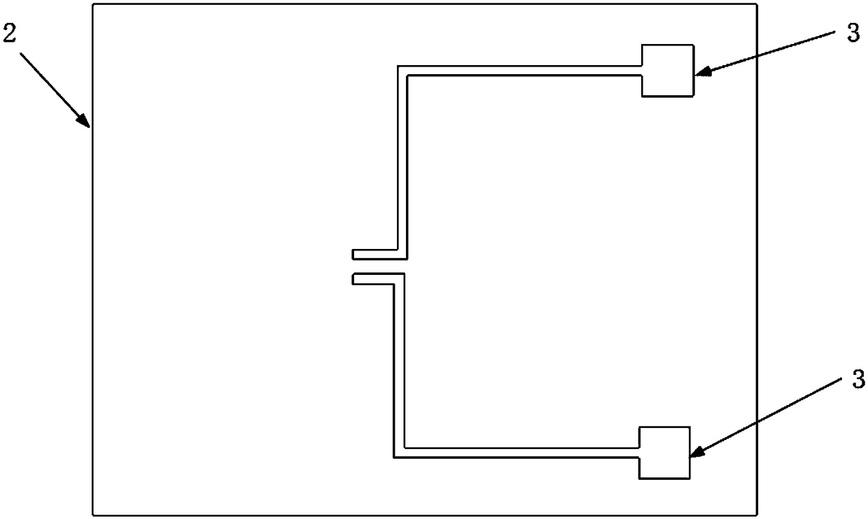
[0032] combine Figure 1-4 , a high-impact inertial microfluidic power switch of the present invention includes a base 1, a cover plate 2, two metal electrodes 3, a microchannel 5, and metal droplets; the cover plate 2 is located at the upper end of the base 1, between the two The substrate 1 is provided with a microchannel 5, and the metal electrode 3 is arranged on the cover plate 2; the microchannel 5 includes a U-shaped liquid reservoir 6, a first capillary valve 7, and a second capillary valve 8 , the third capillary valve 9, the fourth capillary valve 10, the fifth capillary valve 12, the sixth capillary valve 13, the seventh capillary valve 14, the eighth capillary valve 15, the gas guide channel 11; In the reservoir 6; the first capillary valve...


PUM


Abstract

The invention discloses a high impact inertia micro-fluid power connection switch and a manufacturing method thereof. The high impact inertia micro-fluid power connection switch comprises a base, a cover plate, a metal electrode, a micro-channel and metal droplets. The cover plate is arranged on the upper end of the base. The micro-channel is arranged on the base. The metal electrode is arranged on the cover plate. The micro-channel comprises a U-shaped liquid storage tank, capillary valves and an air guide channel. The metal droplets are arranged in the U-shaped liquid storage tank. The firstcapillary valve is connected with the U-shaped liquid storage tank. The second capillary valve is connected with the first capillary valve, and the other end is connected with the third capillary valve. The third capillary valve is connected with the second capillary valve, and the other end is connected with the fourth capillary valve. The fourth capillary valve is connected with the third capillary valve. The fifth capillary valve is connected with the sixth capillary valve. The other end of the sixth capillary valve is connected with the seventh capillary valve. The seventh capillary valveis connected with the sixth capillary valve, and the other end is connected with the eighth capillary valve. The eighth capillary valve is connected with the seventh capillary valve, and the other end is connected with the U-shaped liquid storage tank. The fourth capillary valve and the fifth capillary valve are connected through the air guide channel. The switch can identify the fuze ambient force.

Description

technical field [0001] The invention belongs to the technical field of microfluidic chips, in particular to a high-impact inertial microfluidic power switch and a manufacturing method thereof. Background technique [0002] The microfluidic inertia switch is a new type of switch proposed on the basis of micromechanical inertial switch and microfluidic technology. The microfluidic inertia switch is a system that manipulates a small volume of fluid to circulate in tiny channels or components, where the size of the channels and components is tens to hundreds of microns. Different from the traditional micromechanical switch, the microfluidic inertial switch generally uses metal droplets as the working fluid, and its working principle is that when the metal droplets are subjected to a certain acceleration load, they will reach the position of the fixed signal electrode through the microchannel, and then Turn on the switch. This working mode can overcome the problems of tradition...

Claims


Application Information

Patent Timeline
IPC IPC(8): H01H29/00H01H11/00
CPCH01H11/00H01H29/002
Inventor 聂伟荣李嘉杰黄刘刘国伟
Owner NANJING UNIV OF SCI & TECH
Why Eureka
Try Eureka