Ventilation and heat dissipation power cable channel management system

A power cable, ventilation and heat dissipation technology, applied in the field of power cables, can solve the problems of poor heat dissipation of cables, low safety, and detachment of transmission cables, etc., achieve good control and management functions, good overall stability, and ensure the effect of power transmission efficiency

Inactive Publication Date: 2018-06-15
毛根善
View PDF0 Cites 1 Cited by
  • Summary
  • Abstract
  • Description
  • Claims
  • Application Information

AI Technical Summary

Problems solved by technology

[0010] First, the management and control degree of the existing cable channel is low, the degree of intelligence and automation is low, and the adjustment and adaptability are poor;
[0011] Second, the existing cable trench management system requires a large amount of air-conditioning resources for heat dissipation, but the exhaust volume is large, and the exhaust gas cannot be recycled, resulting in high cost;
[0012] Third, the power cable trench is backfilled with fine sand, which is not conducive to the inspection and maintenance of the operation department, and the heat dissipation of the cable is poor during operation;
[0013] Fourth, when the cable bracket is used in the power cable channel, the heat dissipation of the cable channel is poor. Due to the lack of air convection, the cable generates serious heat and reduces the operating life of the cable;
[0014] Fifth, limited to the problem of land occupation, the power cable trenches in the city cannot build ventilation pavilions and other buildings above the ground;
[0015] Its six, in the prior art, the cable bracket used for placing cables has poor stability when fixing the power transmission cable, and the power transmission cable is easily detached from the bracket, with poor stability and low safety

Method used


Image

  • Ventilation and heat dissipation power cable channel management system
  • Ventilation and heat dissipation power cable channel management system
  • Ventilation and heat dissipation power cable channel management system

Examples


Embodiment Construction

[0042] Specific embodiments are given below in conjunction with the accompanying drawings, and the technical solution of the present invention is further clearly, completely and detailedly described. This embodiment is the best embodiment on the premise of the technical solution of the present invention, but the protection scope of the present invention is not limited to the following embodiments.

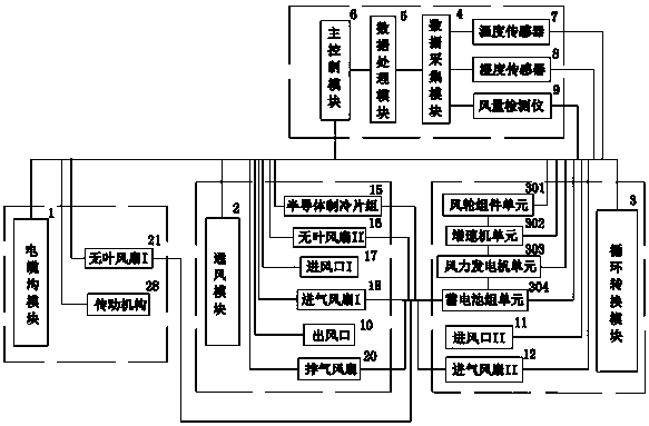
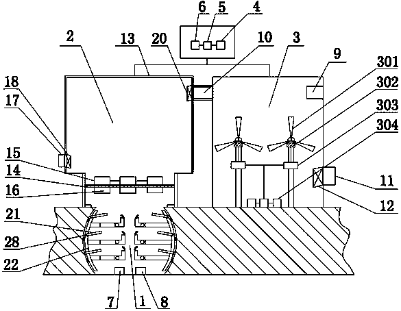
[0043] Such as Figure 1-2 As shown, a ventilation and heat dissipation power cable trench management system includes a cable trench module 1, a ventilation module 2, a cycle conversion module 3, a data acquisition module 4, a data processing module 5 and a main control module 6, a cable trench module 1, a ventilation module Module 2, cyclic conversion module 3, data acquisition module 4, and data processing module 5 are respectively connected to the main control module 6. Each module cooperates closely and has strong logic, which can well realize the control and management functio...


PUM


Abstract

The invention discloses a ventilation and heat dissipation power cable channel management system. The ventilation and heat dissipation power cable channel management system comprises a cable channel module, a ventilation module, a circulation conversion module, a data acquisition module, a data processing module and a main control module; and the main control module is connected with the cable channel module, the ventilation module, the circulation conversion module, the data acquisition module and the data processing module separately. The ventilation and heat dissipation power cable channelmanagement system is novel in design, compact in structure, convenient and efficient as a whole, and has better ventilation and heat dissipation performance on the cable channel and is more automaticand intelligent and is accurate in control; and heat and cold exchange convection can be realized, and wind power also can be used for power generation to realize air circulation conversion, so that the cost is greatly lowered, reasonable resource utilization is realized, the power transmission efficiency of the cable is ensured, and high overall stability and high safety performance are achieved.

Description

technical field [0001] The invention relates to the technical field of power cables, and more specifically, to a ventilation and heat dissipation power cable channel management system. Background technique [0002] The cable trench is an underground pipeline for laying and replacing electric power or telecommunication cable facilities, and it is also an enclosure structure for the cable facilities to be laid. There are rectangular, circular, arched and other pipeline structures. [0003] The layout of cable trenches in power plants and substations is related to field equipment and terrain conditions, but both indoor and outdoor cable trenches generally have the following characteristics: [0004] First, the cable trench is a trench with a cover. The cover must be uncovered when laying and maintaining cables, which is very cumbersome and inconvenient. It is also easy to accumulate stolen goods and water in the trench. However, due to the simple civil construction and low cost...

Claims


Application Information

Patent Timeline
Patent Type & Authority Applications(China)
IPC IPC(8): H02G3/04H02G3/02H02G3/03
CPCH02G3/0456H02G3/02H02G3/03H02G3/0412
Inventor 毛根善
Owner 毛根善
Why Eureka
Try Eureka