
Compact-type thermoelectric power generation device

A thermoelectric power generation, compact technology, used in generators/motors, electrical components, etc., can solve the problems of difficult heat exchange enhancement at the hot end of thermoelectric devices, limiting the power increase of thermoelectric generators, and limited installation of thermoelectric devices. Improve overall thermoelectric performance and energy utilization, flexible configuration, and improve service life

Pending Publication Date: 2018-06-15
UNIV OF SCI & TECH BEIJING
View PDF7 Cites 0 Cited by
  • Summary
  • Abstract
  • Description
  • Claims
  • Application Information

AI Technical Summary

Problems solved by technology

[0003] First of all, in traditional thermoelectric power generation devices, thermoelectric devices are installed near heat sources, such as waste heat flue gas pipes, high-temperature walls, etc. Due to the limitation of installation locations, the number of thermoelectric devices installed is limited, which limits the power increase of thermoelectric generators;
[0004] Secondly, the traditional thermoelectric power generation device only enhances the heat exchange of the cold end of the thermoelectric device. Due to the limitation of the installation location and installation method, it is difficult to enhance the heat exchange of the hot end of the thermoelectric device. The coefficient is usually very low, which further increases the overall thermal resistance and reduces the thermoelectric conversion efficiency;
[0005] Thirdly, for traditional thermoelectric generators, due to the scattered installation of thermoelectric devices, each thermoelectric device needs to be equipped with a separate cooler, and the cooling system of the cold end is relatively complicated.

Method used


Image

  • Compact-type thermoelectric power generation device
  • Compact-type thermoelectric power generation device
  • Compact-type thermoelectric power generation device

Examples


Embodiment Construction

[0032] In order to make the technical problems, technical solutions and advantages to be solved by the present invention clearer, the following will describe in detail with reference to the drawings and specific embodiments.

[0033] The invention provides a compact thermoelectric power generation device aiming at the prior art.

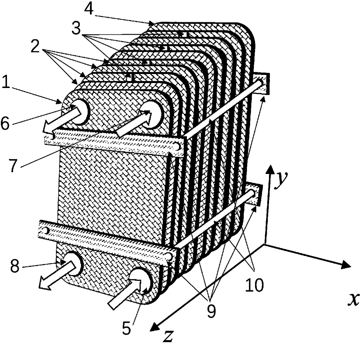
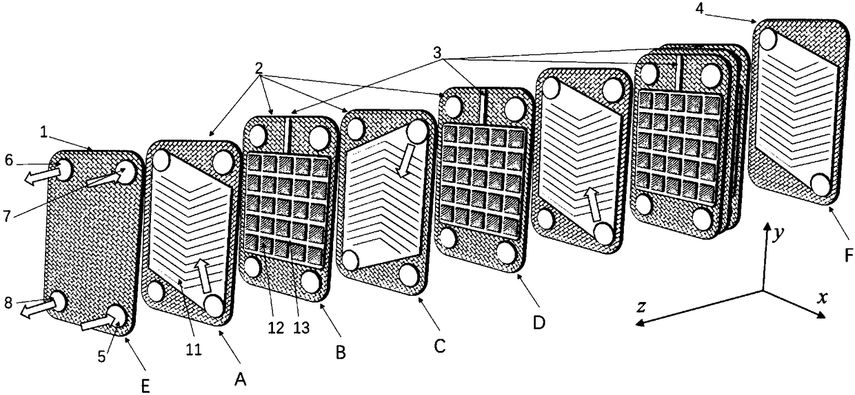
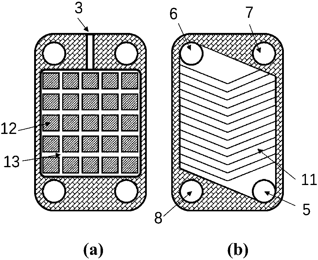
[0034] Such as figure 1As shown, the device includes a compact thermoelectric power generation module, a thermal fluid heater 16, a cold fluid cooler 17, a thermal fluid circulation pump 14, a cold fluid circulation pump 15, cold / hot fluid pipelines, etc., wherein the compact thermoelectric power generation The module is composed of front cover deflector 1, A-B-C-D series deflector combination 2, and rear end cover deflector 4. The compact thermoelectric power generation module has circulation channels for cold fluid and hot fluid, among which the cold fluid The inlet passage 5, the cold fluid outlet passage 6 and the cold fluid pipeline, the cold f...


PUM


Abstract

The invention provides a compact-type thermoelectric power generation device and belongs to the engineering thermophysics and new energy cross technical field. The device comprises a compact-type thermoelectric power generation module, a thermal fluid heater, a cold fluid cooler, a thermal fluid circulating pump, a cold fluid circulating pump and cold / thermal fluid pipelines and the like. The compact-type thermoelectric power generation module is formed by a front end cover guide plate, an A-B-C-D series guide plate combination and a back end cover guide plate, which are stacked up in sequence. The compact-type thermoelectric power generation module has cold fluid and thermal fluid circulation channels, wherein a cold fluid inlet channel and a cold fluid outlet channel form a cold fluid circulation system with the cold fluid pipeline, the cold fluid circulating pump and the cold fluid cooler, and a thermal fluid inlet channel and a thermal fluid outlet channel form a thermal fluid circulation system with the thermal fluid pipeline, the thermal fluid circulating pump and the thermal fluid heater. A plurality of thermoelectric devices are arranged between cold fluid and thermal fluid guide plates in the compact-type thermoelectric power generation module, and the thermoelectric devices convert the heat into electric energy and output the electric energy.

Description

technical field [0001] The invention relates to the interdisciplinary technical fields of engineering thermophysics and new energy, in particular to a compact thermoelectric power generation device. Background technique [0002] Under the action of temperature difference, thermoelectric devices can convert thermal energy into electrical energy (Sai ​​shell effect), and semiconductor thermoelectric devices have high thermoelectric conversion efficiency. In a traditional thermoelectric power generation system, a thermoelectric device is directly in contact with a heat source, or is installed on a high-temperature wall of a heat source (such as a pipe wall). The traditional thermoelectric power generation device has the following disadvantages: [0003] First of all, in traditional thermoelectric power generation devices, thermoelectric devices are installed near heat sources, such as waste heat flue gas pipes, high-temperature walls, etc. Due to the limitation of installation...

Claims


Application Information

Patent Timeline
IPC IPC(8): H02N11/00
CPCH02N11/002
Inventor 豆瑞锋温治刘训良
Owner UNIV OF SCI & TECH BEIJING
Learn More