Planetary reducer
A planetary reducer, planetary carrier technology, applied in mechanical equipment, transmission, gear transmission and other directions, can solve the problems of high assembly difficulty, large comprehensive error, inability to transmit torque, etc., and achieves reduced installation difficulty and large transmission ratio. Output, installation location compact effect
Pending Publication Date: 2018-09-21
陕西捷泰智能传动有限公司
View PDF5 Cites 0 Cited by
- Summary
- Abstract
- Description
- Claims
- Application Information
AI Technical Summary
Problems solved by technology
Since the RV reducer has extremely high requirements on the processing and assembly precision of the parts, it is difficult to achieve high-efficiency processing on the existing general-purpose machine tools, and requires expensive special machine tools, so the manufacturing cost is relatively high
The harmonic reducer relies on the deformation of the flex spline to transmit power and motion. The flex spline has high material requirements, short life, and cannot transmit large torque
[0003] The NGWN planetary reducer has a large speed ratio, high precision and compact structure, but the double gears used in the NGWN planetary reducer are difficult to process. Usually each reducer needs three sets of double gears, and three sets of double gears are required. The angle between the teeth must be exactly the same, poor manufacturability and high cost
In addition, due to the characteristics of the planetary reducer as a floating shaft, the three sets of double gears and the gear shaft need to be installed on the planetary carrier. Due to the functional requirements of the planetary carrier, it is usually designed to be composed of multiple The assembly of lantern-shaped structures composed of parts is extremely difficult to assemble, and the comprehensive error is large. The large comprehensive error causes low mechanical efficiency and greatly reduces the life of the product. Therefore, it has not been used in automatic control equipment and various robot products so far. NGWN structure reducer products
Method used
View moreImage
Smart ImageViewing Examples

Examples
specific Embodiment
[0023] Central gear Ⅰ: Z=29M=0.9
[0024] Central gear II: Z=31M=1
[0025] Planetary gear Ⅰ: Z=31M=0.9
[0026] Planetary gear II: Z=29M=1
[0027] Internal gear housing: Z=89M=1
[0028] Output ring gear: Z=91M=0.9
[0029] Output gear ratio: 176.12
Login to View More PUM
 Abstract
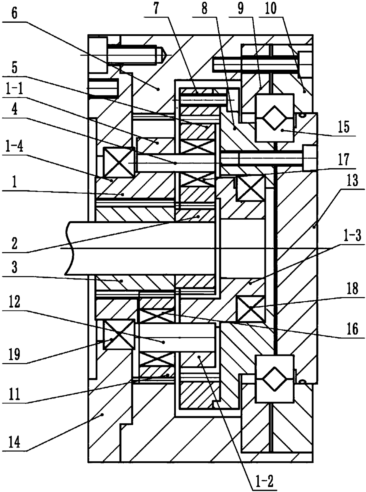
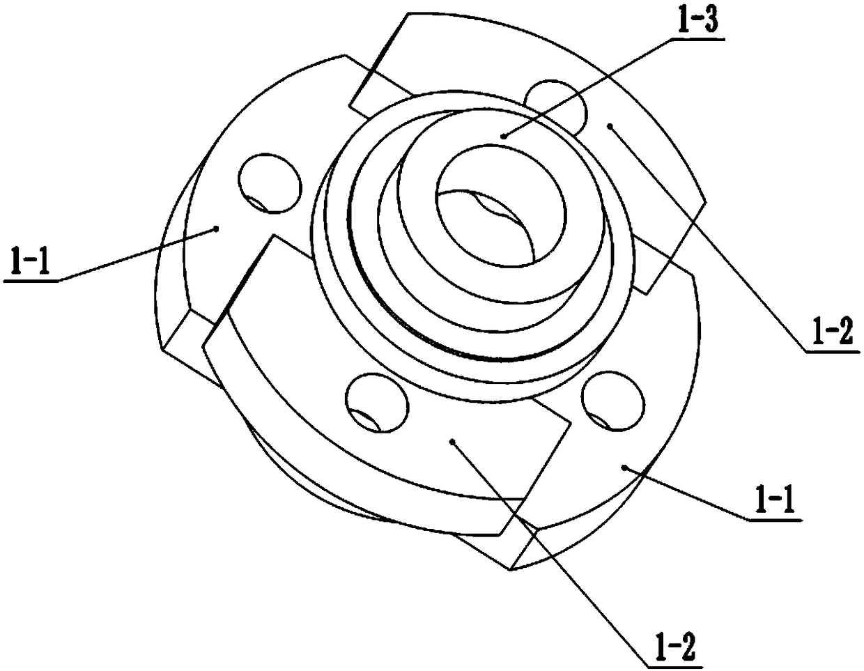
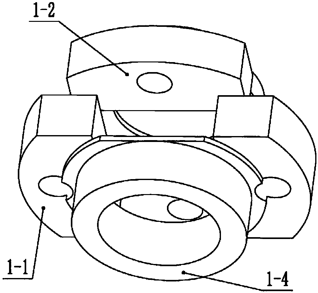
The invention discloses a planetary reducer. A planet carrier of the planetary reducer is installed in an inner gear housing. Two ends of the planet carrier are provided with an annular shaft end I and an annular shaft end II, and the middle is hierarchically and alternately provided with an installing base I and an installing base II. The installing base I and the installing base II are respectively provided with a planetary gear I and a planetary gear II. The center of the planet carrier is provided with a center gear I and a center gear II. The left end of the inner gear housing is fixedlyprovided with an input flange. The annular shaft end I is sheathed with an output connector through a bearing, the left end face of the output connector is fixedly provided with an output inner gear ring and the right end face is fixedly provided with the input flange. The annular shaft end II is installed at the center of the input flange through a bearing. The planetary gear II is meshed with the center gear II and the inner gear housing. The planetary gear I is meshed with the center gear I and the output inner gear ring. Through staggered installation of the planet gears, and respective driving of the two center gears, the planetary reducer is capable of reducing the manufacturing cost and the installing difficulty, enabling the size of a complete machine to be smaller, and realizing the output in large transmission ratio.
Description
technical field [0001] The invention relates to the technical field of reducers, in particular to a planetary reducer. Background technique [0002] The robot joint reducer widely adopts RV reducer and harmonic reducer. Since the RV reducer has extremely high requirements on the processing and assembly precision of the parts, it is difficult to achieve high-efficiency processing on the existing general-purpose machine tools, and requires expensive special-purpose machine tools, so the manufacturing cost is relatively high. The harmonic reducer relies on the deformation of the flexspline to transmit power and motion. The flexspline has high material requirements, short life, and cannot transmit large torque. [0003] The NGWN planetary reducer has a large speed ratio, high precision and compact structure, but the double gears used in the NGWN planetary reducer are difficult to process. Usually each reducer needs three sets of double gears, and three sets of double gears are ...
Claims
Login to View More Application Information
Patent Timeline
 Patent Type & Authority Applications(China)
IPC IPC(8): F16H1/36F16H57/023
CPCF16H1/36F16H57/023
Inventor 乔维华刘邵全段建丽刘莎李新刚
Owner 陕西捷泰智能传动有限公司