
Method for manufacturing automotive equipment capable of automatically punching plastic nozzles

A manufacturing method and automatic technology, applied in applications, household components, household appliances, etc., can solve the problems of unguaranteed product appearance quality, affecting the production progress of the company's quality, increasing labor costs, etc., to promote stability, prevent ground Fatigue damage and easy handling

Inactive Publication Date: 2018-06-19
苏州胜利高睿智能汽车制造有限公司
View PDF1 Cites 7 Cited by
  • Summary
  • Abstract
  • Description
  • Claims
  • Application Information

AI Technical Summary

Problems solved by technology

[0002] Plastic products that have undergone injection molding need to be processed by cutting the nozzle or hot-melt nozzle, and the nozzle is used to inject liquid in the injection molding process, and it is cooled and shaped after the injection molding process; common plastic products, the shear nozzle is Manually completed, manual operation not only wastes time but also increases labor costs, and the appearance quality of the product cannot be guaranteed, especially for mass production, the production efficiency of manual secondary processing is too low and the quality is poor, which will eventually affect the entire production The progress and the quality of the company; and for some factories, because of the high mobility of personnel, new employees need to be trained and guided frequently, which puts a lot of pressure on the company's production

Method used


Image

  • Method for manufacturing automotive equipment capable of automatically punching plastic nozzles
  • Method for manufacturing automotive equipment capable of automatically punching plastic nozzles
  • Method for manufacturing automotive equipment capable of automatically punching plastic nozzles

Examples


Embodiment Construction

[0018] The following will clearly and completely describe the technical solutions in the embodiments of the present invention with reference to the accompanying drawings in the embodiments of the present invention. Obviously, the described embodiments are only some, not all, embodiments of the present invention. Based on the embodiments of the present invention, all other embodiments obtained by persons of ordinary skill in the art without making creative efforts belong to the protection scope of the present invention.

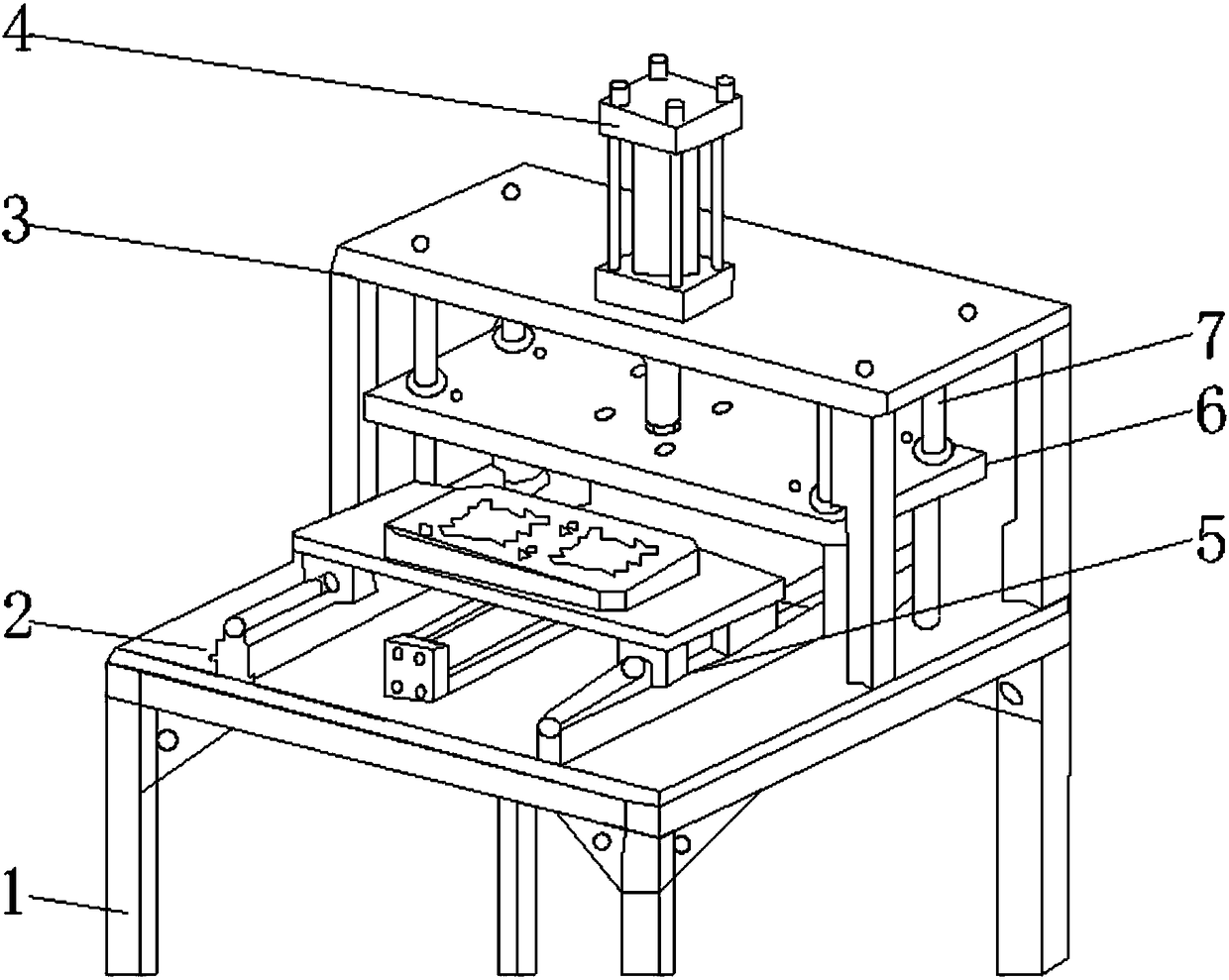
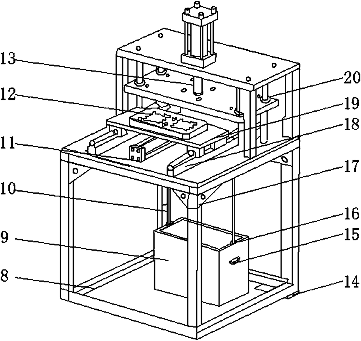
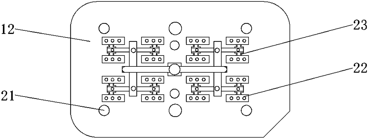
[0019] see Figure 1-5 , a kind of embodiment that the present invention provides: a kind of automatic plastic cutting nozzle manufacturing method for automobile, comprises process table 2, machine top plate 3, pre-pressing plate 25 and nozzle collecting box 9, and the surface of process table 2 is equipped with conveying cylinder 11, The transmission cylinder 11 is controlled by the electrical system, and guide rails 18 are installed on the surface of the pro...


PUM


Abstract

The invention discloses a method for manufacturing automotive equipment capable of automatically punching plastic nozzles. The equipment comprises a process table, a mechanical propping plate, a prepressing plate and a nozzle collecting box, wherein a conveying air cylinder is arranged on the surface of the process table; a lower die plate is arranged on the top of a moving plate; fixing columns are arranged on the surface, at two sides of guide rails, of a process table; the mechanical propping plate is arranged on the tops of the fixing columns; a punching cylinder is arranged on the top ofthe mechanical propping plate; a pressure bearing column is arranged at the output end of the punching cylinder; an upper die fixing plate is arranged at the bottom of the pressure bearing column; theprepressing plate is arranged at the bottom end of the upper die fixing plate; pillars are uniformly arranged at the bottom of the process table; a supporting bottom plate is arranged at the bottomsof the support columns; and the nozzle collecting box is arranged below the process table inside the supporting bottom plate. The equipment disclosed by the invention has the beneficial effects that through a series of structures, plastic products can be accurately placed in the process of punching the plastic nozzles; the punching accuracy and the punching efficiency are increased; and the subsequent processing is facilitated.

Description

technical field [0001] The invention relates to the technical field of auto parts, in particular to a method for manufacturing an automatic plastic-cut nozzle for an automobile. Background technique [0002] Plastic products that have undergone injection molding need to be processed by cutting the nozzle or hot-melt nozzle, and the nozzle is used to inject liquid in the injection molding process, and it is cooled and shaped after the injection molding process; common plastic products, the shear nozzle is Manually completed, manual operation not only wastes time but also increases labor costs, and the appearance quality of the product cannot be guaranteed, especially for mass production, the production efficiency of manual secondary processing is too low and the quality is poor, which will eventually affect the entire production The progress and the quality of the company; and for some factories, because of the high mobility of personnel, new employees need to be trained and ...

Claims


Application Information

Patent Timeline
IPC IPC(8): B29C45/38B29L31/30
CPCB29C45/382B29L2031/30
Inventor 龙盖清
Owner 苏州胜利高睿智能汽车制造有限公司
Learn More