
Secondary penetrant device for heat transfer printing

A technology of thermal transfer printing and permeation device, applied in transfer printing, rotary printing machine, printing and other directions, can solve the problems such as the inability of the fiber to restore fluffy immediately, the dye penetration is not enough, and the work efficiency is reduced, and the design structure is simple and clear. The effect of air outlet is obvious and the effect of improving production efficiency

Pending Publication Date: 2018-06-19
刘林玉
View PDF6 Cites 2 Cited by
  • Summary
  • Abstract
  • Description
  • Claims
  • Application Information

AI Technical Summary

Problems solved by technology

[0005] In order to solve the above problems, the present invention discloses a thermal transfer printing secondary penetration device. After the dyeing process of high-weight flannelette is completed, the fibers that have been flattened on the surface of the fluffy fleece carrier cannot immediately restore the fluffy state. It is beautiful and reduces work efficiency. At the same time, after the dyeing process is completed, the fabric body has a lot of waste heat and cannot be used, resulting in a waste of resources.

Method used


Image

  • Secondary penetrant device for heat transfer printing

Examples


Embodiment 1

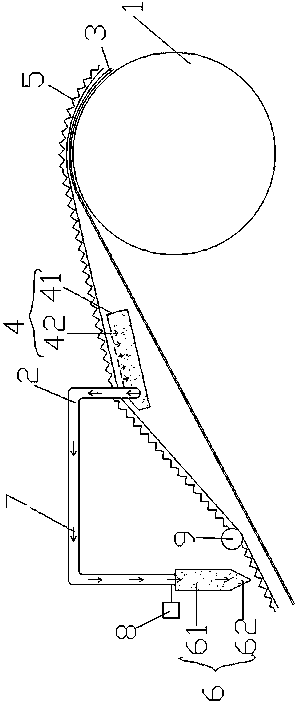
[0025] Embodiment 1: see figure 1Now, a thermal transfer printing secondary permeation device provided by the present invention will be described. A heat transfer printing secondary penetration device, comprising a heat roller 1 and a heat-resistant air pipe 2, characterized in that: the heat roller 1 is connected to a heat transfer printing machine, and is wrapped with a high-temperature resistant blanket 3, and the high-temperature resistant blanket 3 The heat extractor 4 is arranged at the upper end, the heat extractor 4 includes a box body 41, and the air vent 42 is arranged on the surface of the box body 41, and one end of the heat-resistant air pipe 2 passes through the air vent hole 41 and the box body of the heat extractor 4 41 connection, the other end of the heat-resistant air pipe 2 is connected to the air outlet device, the air outlet device is an air knife 6, and the air knife 6 includes a knife body 61 and an air knife edge 62, and the air knife edge 62 is design...

Embodiment 2

[0026] Example 2: see figure 1 , as an improvement of the present invention, the air holes 42 are uniformly arranged on the upper surface or the left and right surfaces of the box body 41 . Ventilation holes 42 are evenly arranged on the surface of the box body 41, and the hot gas in the cloth can be transmitted to the inside of the box body 41 of the heat extractor 4 while connecting the heat-resistant air pipe 2, and the vaporized dye can be evenly and quickly penetrated into the second deep layer The bottom of the fabric, the design structure is simple and clear, and it is closely connected with each component without interfering with each other, which is easy to maintain during the use of the product in the future.

Embodiment 3

[0027] Embodiment 3: see figure 1 , as an improvement of the present invention, the heat-resistant gas pipe 2 is an inverted U-shaped pipe. The heat-resistant gas pipe 2 is designed as an inverted U-shaped pipe according to the cloth transfer direction, which has a simple design structure, convenient installation, and good effect of transferring hot gas.


PUM


Abstract

The invention discloses a secondary penetrant device for heat transfer printing. The secondary penetrant device for heat transfer printing comprises a heat roller and a heat-resisting air pipe. The heat roller is connected with a heat transfer printing machine; a high-temperature-resistant blanket is wrapped on the periphery of the heat roller; a heat extraction body is arranged on the upper end of the high-temperature-resistant blanket, and comprises a tank body; air holes are formed in a surface of the tank body; one end of the heat-resisting air pipe is connected with the tank body of the heat extraction body through the air holes; the other end of the heat-resisting air pipe is connected with an air outlet device; the air outlet device is an air knife; the heat extraction body is designed after a heat transfer printing machine process; a cloth material subjected to high-temperature transfer printing is discharged from a cloth outlet; air presses on a surface of the multiple air holes of the cloth material, so that hot air in the cloth material is extracted into the tank body; the cloth material is air-extracted by the heat extraction body, so that a dye vaporized on a surface of the cloth material is promoted to be secondarily adsorbed to the cloth material so as to arrive at the bottom part of the cloth material from top to bottom since an air flow direction is changed; and the secondary dye is deeply penetrated to the bottom part of the cloth material quickly through high temperature, so that a printing effect is improved.

Description

technical field [0001] The invention relates to the technical field of printing and dyeing, in particular to a thermal transfer printing secondary penetration device. Background technique [0002] Traditional printed textile fabrics are generally made of warp and weft threads and then dyed and printed on the surface. The color effect is flat, the color visual effect is single, the color transition is not natural enough, the layering is not enough, and there is no three-dimensional sensory effect. It can't present bright color highlights, so it can't satisfy the three-dimensional stereoscopic visual effect that high-grade fabrics will present at all. [0003] In contrast, the fabric produced by heat transfer printing process has a stronger three-dimensional pattern. As the viewing angle changes, its color will also change, with different shades, layered on top of each other, like the traditional ink painting method. The "ink accumulation" effect in the painting gives people ...

Claims


Application Information

Patent Timeline
Patent Type & Authority Applications(China)
IPC IPC(8): B41F16/00B41F16/02
CPCB41F16/0093B41F16/02
Inventor 刘林玉
Owner 刘林玉
Learn More