
Downward open type automatic drainage well lid

An automatic drainage and bottom-opening technology, which is applied to drainage structures, waterway systems, water supply devices, etc., can solve the problems of pedestrian and vehicle travel and safety hazards, affecting road safety, drowning people, etc., achieving low cost and wide application range , the effect of simple structure

Inactive Publication Date: 2018-06-19
陈年康
View PDF5 Cites 4 Cited by
  • Summary
  • Abstract
  • Description
  • Claims
  • Application Information

AI Technical Summary

Problems solved by technology

Especially when there is water accumulation on the road, the rainwater system has become saturated. At this time, the sewage pipe with a larger diameter than the rainwater pipe is in an idle state. Because no one opens the sewage manhole cover, the rainwater cannot enter the sewage system and be discharged in time, resulting in a large amount of water accumulation on the road. , causing great hidden dangers to the travel and safety of pedestrians and vehicles, and even the phenomenon of drowning people on the road, it is common for vehicles to be flooded, and strange phenomena such as boating and fishing on the road
However, manual opening of the manhole cover has the following disadvantages: when there is water accumulation on the road surface, the manhole cover cannot be opened in time at the first time.
After the well cover is opened, most of the warning signs cannot be set up, and personnel are required to guard the wellhead. If the wellhead is on the roadway, the guards will be very dangerous and may easily cause traffic accidents and other problems.
[0004] Due to the unreasonable design of the drainage pipes or the low location of some road sections, backflow will occur when the rainfall is large, which will further affect road safety

Method used


Image

  • Downward open type automatic drainage well lid
  • Downward open type automatic drainage well lid
  • Downward open type automatic drainage well lid

Examples


Embodiment Construction

[0027] The present invention will be described in further detail below in conjunction with the accompanying drawings.

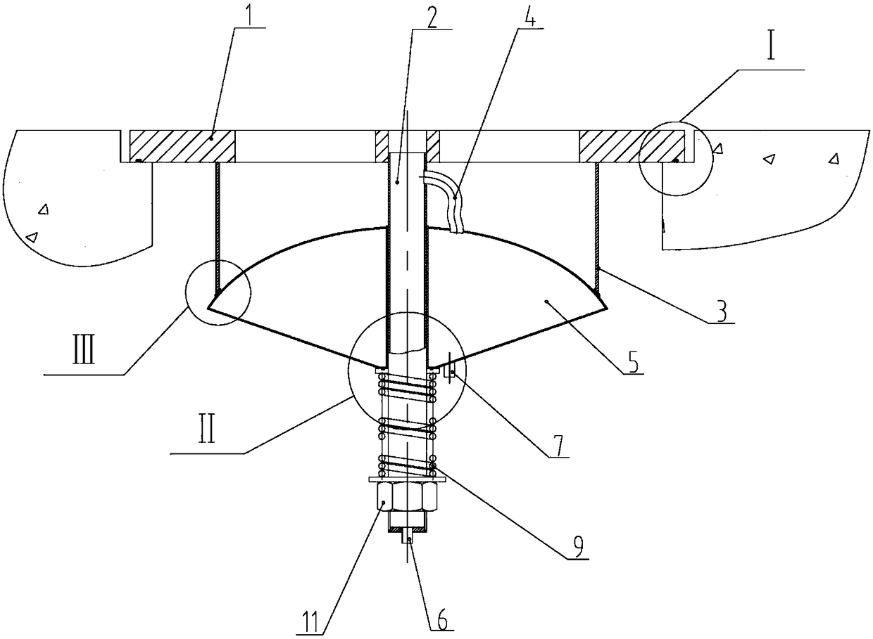
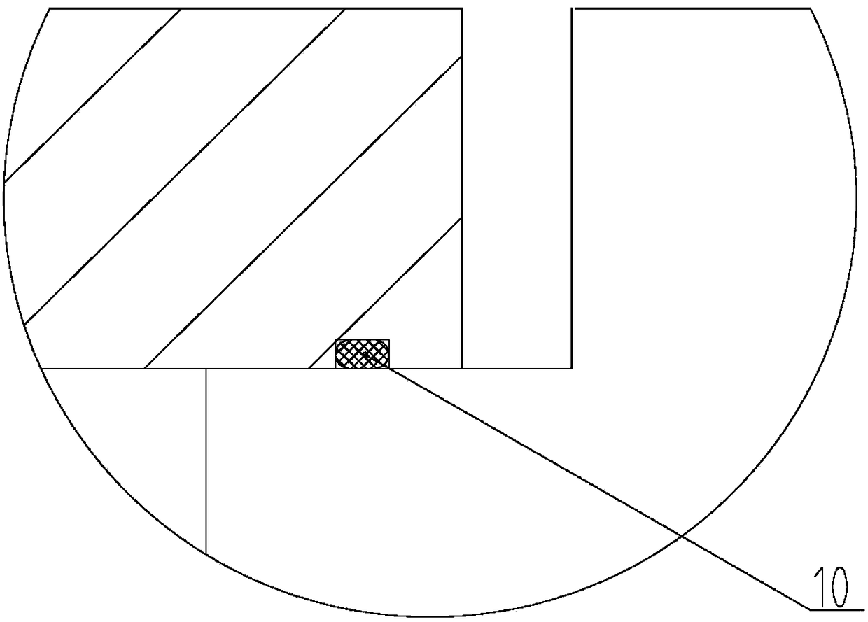
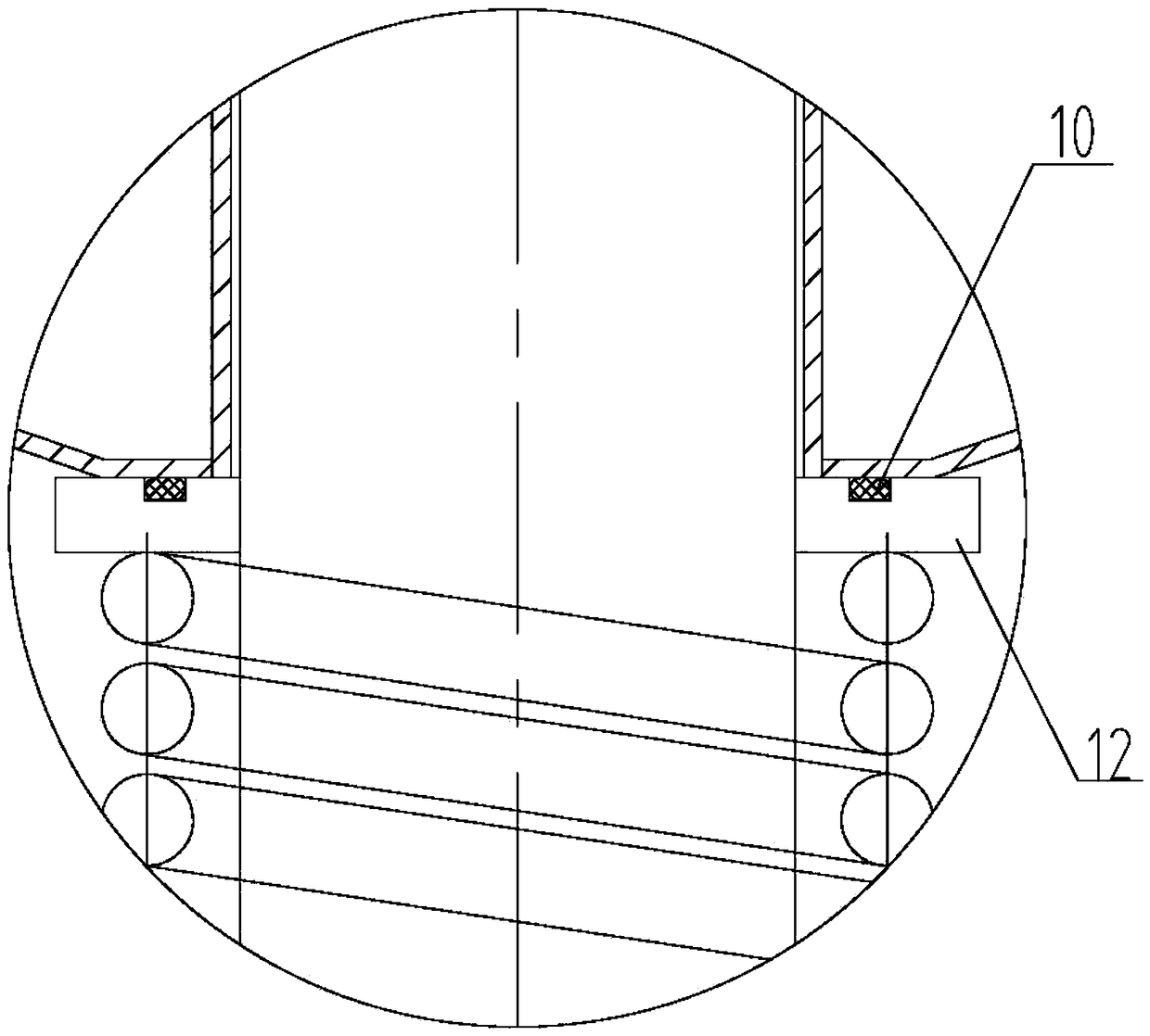
[0028] see Figure 1-Figure 5 , the present invention includes: a well cover 1, a support ring 3 and a water storage bin 5, the well cover 1 includes a solid part of the outer ring and a hollow part of the inner ring, and the center of the well cover 1 is provided with a drainage hole. The lower surface of the well cover 1 is provided with a supporting ring 3 along the circumferential direction; the bottom of the well cover 1 is provided with a drainage pipe 2 connected with the drainage hole; A number of water inlets are opened, and a water outlet is opened at the bottom of the water storage bin 5; the water storage bin 5 is arranged in close contact with the edge of the support ring 3 through an elastic device.

[0029] The water storage bin 5 is in a hemispherical shape protruding upwards, and the raised part extends into the support ring 3 ; the center o...


PUM


Abstract

The invention belongs to the field of urban drainage systems, and particularly relates to a downward open type automatic drainage well lid. The well lid comprises a well lid body, an outer ring of thewell lid body is a solid part, an inner ring of the well lid body is a hollowed-out part, and a drainage hole is formed in the center of the well lid body; a supporting ring is arranged on the lowersurface of the well lid body in the circumferential direction; a drainage pipe communicated with the drainage hole is arranged below the well lid body, and a water storage bin is movably arranged on the drainage pipe; a plurality of water inlets are uniformly formed in the top of the water storage bin in the circumferential direction, and a water outlet is formed in the bottom of the water storagebin; the water storage bin is tightly attached to the edge of the supporting ring through an elastic device. The water storage bin and the supporting ring are tightly attached through the elastic device, so that the well lid device is especially suitable for road sections low in terrain, and no backward flowing phenomenon is caused. In addition, the well lid is simple in structure and low in cost, and a worker does not need to watch the well lid during use, no other peripheral equipment is used, and the application range is wide.

Description

technical field [0001] The invention belongs to the field of urban drainage systems, and in particular relates to a bottom-opening automatic drainage manhole cover. Background technique [0002] Urban drainage systems include stormwater wells and sewage wells. When there is rainfall, the current urban road pavement drainage mainly discharges road surface rainwater into the urban drainage pipe network through the water inlet hole of the rain well cover plate. [0003] When the rainfall is small, the rainwater can be drained in time through the water inlet hole on the well cover. When extreme weather occurs, the rainwater cannot be drained through the rainwater well in time, and the phenomenon of poor drainage will occur, causing a large amount of water to accumulate on the road surface. At this time, it is necessary to manually cover the road surface to increase the drainage of accumulated water. Especially when there is water accumulation on the road, the rainwater system...

Claims


Application Information

Patent Timeline
Patent Type & Authority Applications(China)
IPC IPC(8): E03F5/06
CPCE03F5/06
Inventor 陈年康
Owner 陈年康
Learn More