Unpowered water wave pump

A water wave and power technology, applied in the field of non-powered water wave pumps, can solve the problems of continuous high-pressure water supply, low water wheel efficiency, and low efficiency, and achieve the effects of small vibration, small footprint, and non-destructive effects

Active Publication Date: 2018-06-19
刘英学
View PDF7 Cites 0 Cited by
  • Summary
  • Abstract
  • Description
  • Claims
  • Application Information

AI Technical Summary

Problems solved by technology

The efficiency of the water wheel is extremely low, it needs to occupy a large space, the height of the water head that can be raised is very small, and the noise generated is very large; the working principle of the water hammer pump is to use two valves that are frequently switched to cause the water to flow through the inside of the pump body. The velocity of the water flow changes, and some of the water reaches the high-pressure water head, but its efficiency is also low, and the two frequently switched valves will generate large vibration and noise, and are easily damaged, and cannot provide continuous high-pressure water supply.

Method used


Image

  • Unpowered water wave pump
  • Unpowered water wave pump
  • Unpowered water wave pump

Examples


Embodiment 1

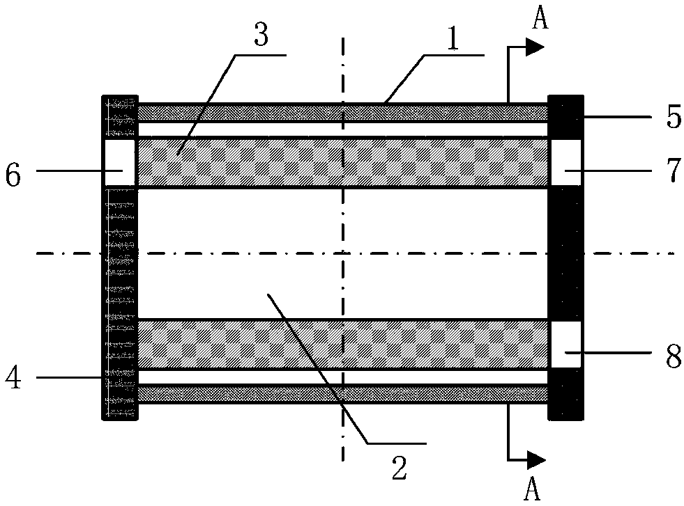
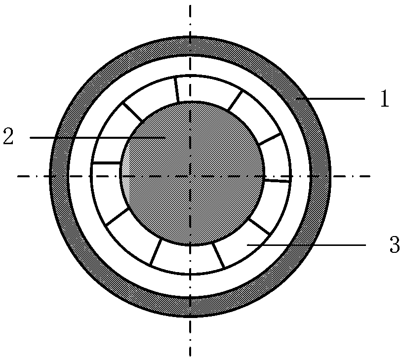
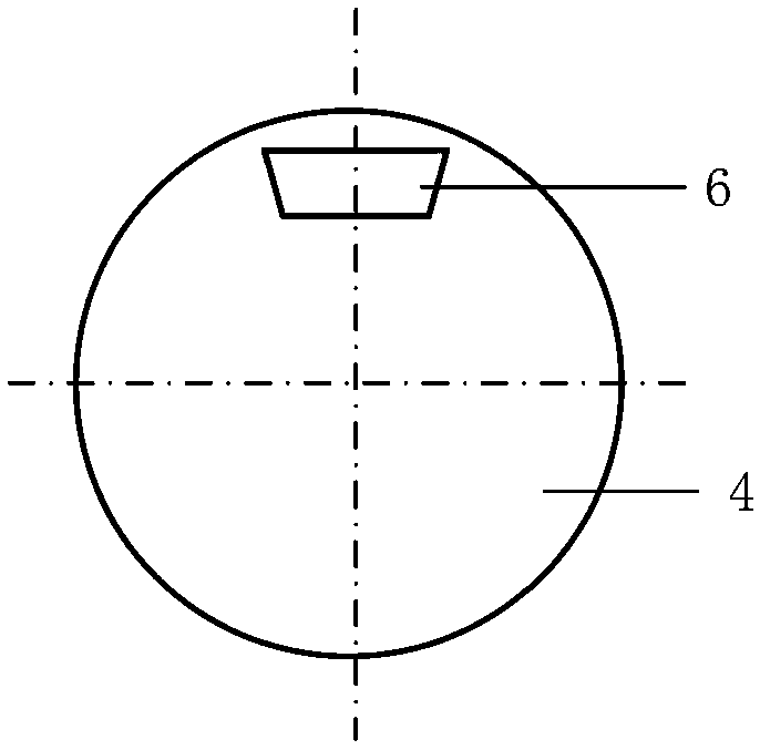
[0021] The unpowered water wave pump in the present embodiment, as figure 1 , figure 2 , image 3 and Figure 4 , including an outer cylinder 1, an inner cylinder 2 is provided inside the outer cylinder 1, the outer cylinder 1 and the inner cylinder 2 are coaxially placed, and there are multiple grooved impellers 3 between the outer cylinder 1 and the inner cylinder 2, and the grooved impellers 3 are Evenly distributed on the circumference, one end of the outer cylinder 1 and the inner cylinder 2 is connected with the front end cover 4 , and the other end is connected with the rear end cover 5 . There is a medium-pressure water inlet 6 on the front-end cover 4, and the medium-pressure water inlet 6 is on the upper edge of the front-end cover 4. The medium-pressure water inlet 6 and the front-end cover 4 have an inclination angle α, and the range of the inclination angle α is 5° to 10° There is a high-pressure water outlet 7 and a low-pressure water outlet 8 on the rear end...

Embodiment 2

[0023] The unpowered water wave pump in this embodiment includes an outer cylinder 1, an inner cylinder 2 is arranged inside the outer cylinder 1, the outer cylinder 1 and the inner cylinder 2 are placed coaxially, and there are multiple grooves between the outer cylinder 1 and the inner cylinder 2 The grid impeller 3 and the grooved grid impeller 3 are evenly distributed on the circumference. One end of the outer cylinder 1 and the inner cylinder 2 is connected to the front end cover 4 , and the other end is connected to the rear end cover 5 . There is a medium pressure water inlet 6 and a low pressure water outlet 8 on the front end cover 4, the medium pressure water inlet 6 is on the lower edge of the front end cover 4, the low pressure water outlet 8 is on the upper edge of the front end cover 4, the medium pressure water inlet 6 and the low pressure water outlet The water outlets 8 all have an inclination angle α with the front end cover 4, and the range of the inclination...

Embodiment 3

[0025] The unpowered water wave pump in this embodiment includes an outer cylinder 1, an inner cylinder 2 is arranged inside the outer cylinder 1, the outer cylinder 1 and the inner cylinder 2 are placed coaxially, and there are multiple grooves between the outer cylinder 1 and the inner cylinder 2 The grid impeller 3 and the grooved grid impeller 3 are evenly distributed on the circumference. One end of the outer cylinder 1 and the inner cylinder 2 is connected to the front end cover 4 , and the other end is connected to the rear end cover 5 . There is a medium-pressure water inlet 6 and a high-pressure water outlet 7 on the front end cover 4, the medium-pressure water inlet 6 is on the lower edge of the front-end cover 4, the high-pressure water outlet 7 is on the upper edge of the front-end cover 4, the medium-pressure water inlet 6 and the high-pressure The water outlet 7 has an inclination angle α with the front end cover 4, and the range of the inclination angle α is 5-10...


PUM


Abstract

The invention relates to an unpowered water wave pump. The pump is composed of an outer cylinder, an inner cylinder, a grooved-gate impeller, a front end cover, a rear end cover, a middle pressure water inlet, a high pressure water outlet and a low pressure water outlet. The unpowered water wave pump is combined with two mechanical work principles of a wave pressure supercharger and a water hammerpump, and breakthrough innovation of structural and process design, work conditions, manners and the like can be achieved. The motion is rotatable, a movable water valve is not needed, vibration is small, the occupied area is small, the noise is low, continuous water outputting is achieved, the pump is simple and compact in structure, not prone to damage, good in reliability, and long in servicelife, and little outer energy output is needed in the earlier stage.

Description

technical field [0001] The invention relates to a non-powered water wave pump. Background technique [0002] At present, the existing non-powered water delivery equipment at home and abroad only has traditional waterwheels and water hammer pumps. The efficiency of the water wheel is extremely low, it needs to occupy a large space, the height of the water head that can be raised is very small, and the noise generated is very large; the working principle of the water hammer pump is to use two valves that are frequently switched on and off to cause the water to flow through the inside of the pump body. The speed of water flow changes, and part of the water reaches the high-pressure water head, but its efficiency is also low, and the two valves that are frequently switched on and off will generate large vibration and noise, and are easily damaged, and cannot provide continuous high-pressure water supply. . Contents of the invention [0003] In view of this, the present inven...

Claims


Application Information

Patent Timeline
Patent Type & Authority Applications(China)
IPC IPC(8): F04D13/04F04D29/40F04D29/18
CPCF04D13/043F04D29/18F04D29/406
Inventor 刘英学
Owner 刘英学
Why Eureka
Try Eureka