Mechanical automatic transmission speed change system

An automatic transmission and mechanical technology, applied in the field of automobile transmission, can solve the problems of long shifting time, poor shifting quality, complicated control technology, etc., and achieve the effect of improving shifting quality and reducing power interruption time.

Pending Publication Date: 2018-06-19
HUAIYIN INSTITUTE OF TECHNOLOGY
View PDF2 Cites 2 Cited by
  • Summary
  • Abstract
  • Description
  • Claims
  • Application Information

AI Technical Summary

Problems solved by technology

However, most of the current all-electric AMTs also have problems such as

Method used


Image

  • Mechanical automatic transmission speed change system
  • Mechanical automatic transmission speed change system

Examples


Embodiment 1

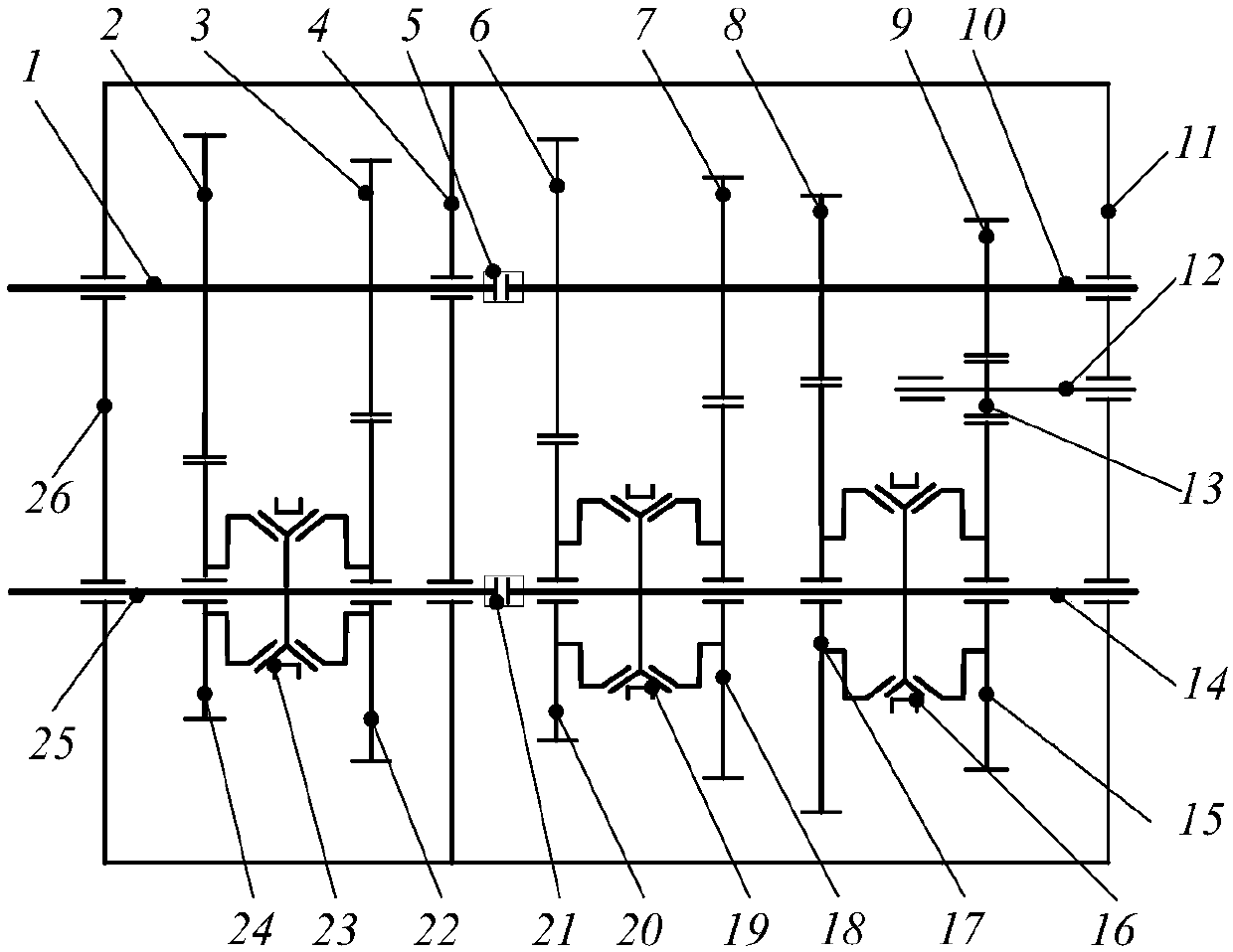
[0018] Embodiment 1 A description of the structure of a transmission system of a five-speed mechanical automatic transmission

[0019] like figure 1 , figure 2 As shown, the five-speed mechanical automatic transmission transmission system consists of a left box body 26, a right box body 11, a support body 4, an input shaft 1, an input shaft 10, an output shaft 25, an output shaft 14, a reverse gear Shaft 12, flexible coupling 5 and 21, first gear driving gear 8, second gear driving gear 7, third gear driving gear 3, fourth gear driving gear 6, fifth gear driving gear 2, reverse gear driving gear 9, first gear Passive gear 17, second gear passive gear 18, third gear passive gear 22, fourth gear passive gear 20, fifth gear passive gear 24, reverse passive gear 15, reverse intermediate gear 13, first reverse synchronizer 16, second and fourth gears Synchronizer 19, third and fifth gear synchronizers 23 are formed.

[0020] The supporting body 4 is located between the left cas...

Embodiment 2

[0029] Embodiment 2 A five-speed mechanical automatic transmission transmission system power transmission route and working principle

[0030] The power transmission route and working process are as follows:

[0031] Neutral. The power is transmitted to the input shaft of the transmission system, and the transmission shift actuator controls each synchronizer not to mesh with any gear driving gear, the power cannot be transmitted to the output shaft of the transmission system, and the transmission is in the neutral position.

[0032] one block. The gear shift actuator of the transmission controls a reverse gear synchronizer 16 to mesh with a first gear driven gear 17, and all the other synchronizers do not mesh with any gear gears. At this time, the power passes through the flexible coupling 5, the second input shaft 10, the first gear driving gear 8, the first gear driven gear 17, the first reverse gear synchronizer 16, the output two shafts 14 and the flexible coupling s...


PUM


Abstract

The invention relates to a mechanical automatic transmission speed change system. The mechanical automatic transmission speed change system is composed of a box body, an input shaft, an output shaft,a reverse gear shaft, driving toothed wheels of various gears, driven toothed wheels of various gears, a reverse gear intermediate toothed wheel, and a plurality of synchronizers. The box body is divided into a left box body and a right box body, a supporting body is arranged between the left box body and the right box body, and the box body is formed by connecting and assembling the left box body, the right box body and the supporting body through bolts or screws; the input shaft is formed by connecting a first input shaft with a second input shaft through a flexible coupling; a transmissiongear driving toothed wheel is machined on the input shaft or fixedly installed on the input shaft through a spline; the output shaft is formed by connecting a first output shaft and a second output shaft through a flexible coupling; the multiple non-adjacent gear synchronizers are fixedly installed on the output shaft through splines, and the two sides of each non-adjacent gear synchronizer are loosely sleeved with the driven toothed wheels of the corresponding gears through bearings; and the reverse gear shaft is sleeved with the reverse gear intermediate toothed wheel. Through the mechanicalautomatic transmission speed change system, the gear shifting time of a mechanical automatic transmission can be shortened advantageously, and the gear shifting quality is improved.

Description

technical field [0001] The invention relates to the technical field of automobile transmission, in particular to an automatic transmission transmission system. Background technique [0002] The automatic shifting of the car makes the vehicle easy to drive, reduces the driver's labor intensity, thereby improving driving safety, and reducing the impact of the driver's technical level on the car's power, economy, emission indicators and smoothness, ensuring the safety of the vehicle's power transmission system. In good working order. Therefore, the automatic transmission of automobiles is widely used, especially in cars and minicars, which gradually enter the family, and unskilled drivers are increasing day by day, the application of automatic transmissions of automobiles has more important significance. [0003] Mechanical automatic transmission (AMT) is based on the existing manual gear mechanical transmission, and an automatic control system is added. Compared with hydraul...

Claims


Application Information

Patent Timeline
IPC IPC(8): F16H3/38F16H57/023
CPCF16H3/38F16H57/023F16H2200/0082F16H2200/0047
Inventor 王程夏晶晶许善珍任远许娣
Owner HUAIYIN INSTITUTE OF TECHNOLOGY
Why Eureka
Try Eureka