[0027] The technical solutions in the embodiments of the present invention will be clearly and completely described below in conjunction with the accompanying drawings in the embodiments of the present invention. Obviously, the described embodiments are only a part of the embodiments of the present invention, rather than all the embodiments. Based on the embodiments of the present invention, all other embodiments obtained by those of ordinary skill in the art without creative work shall fall within the protection scope of the present invention.
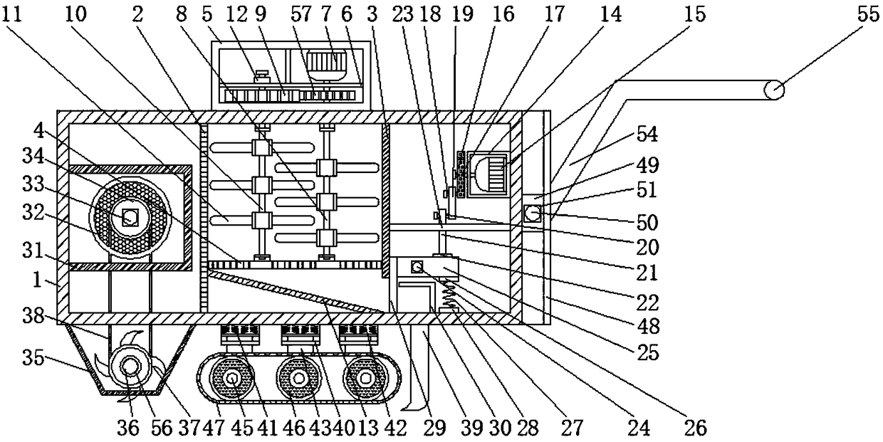
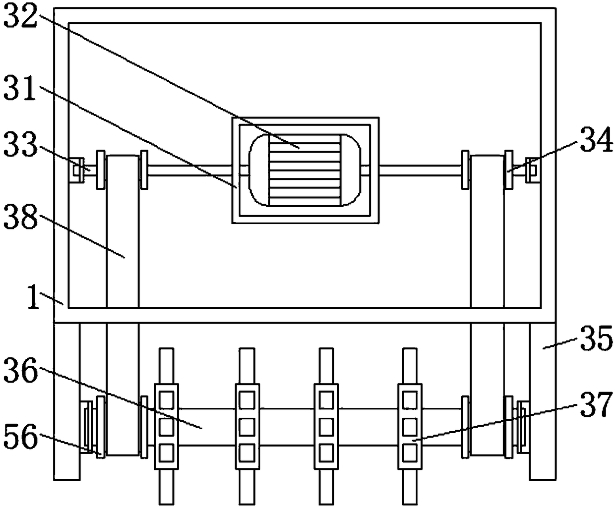
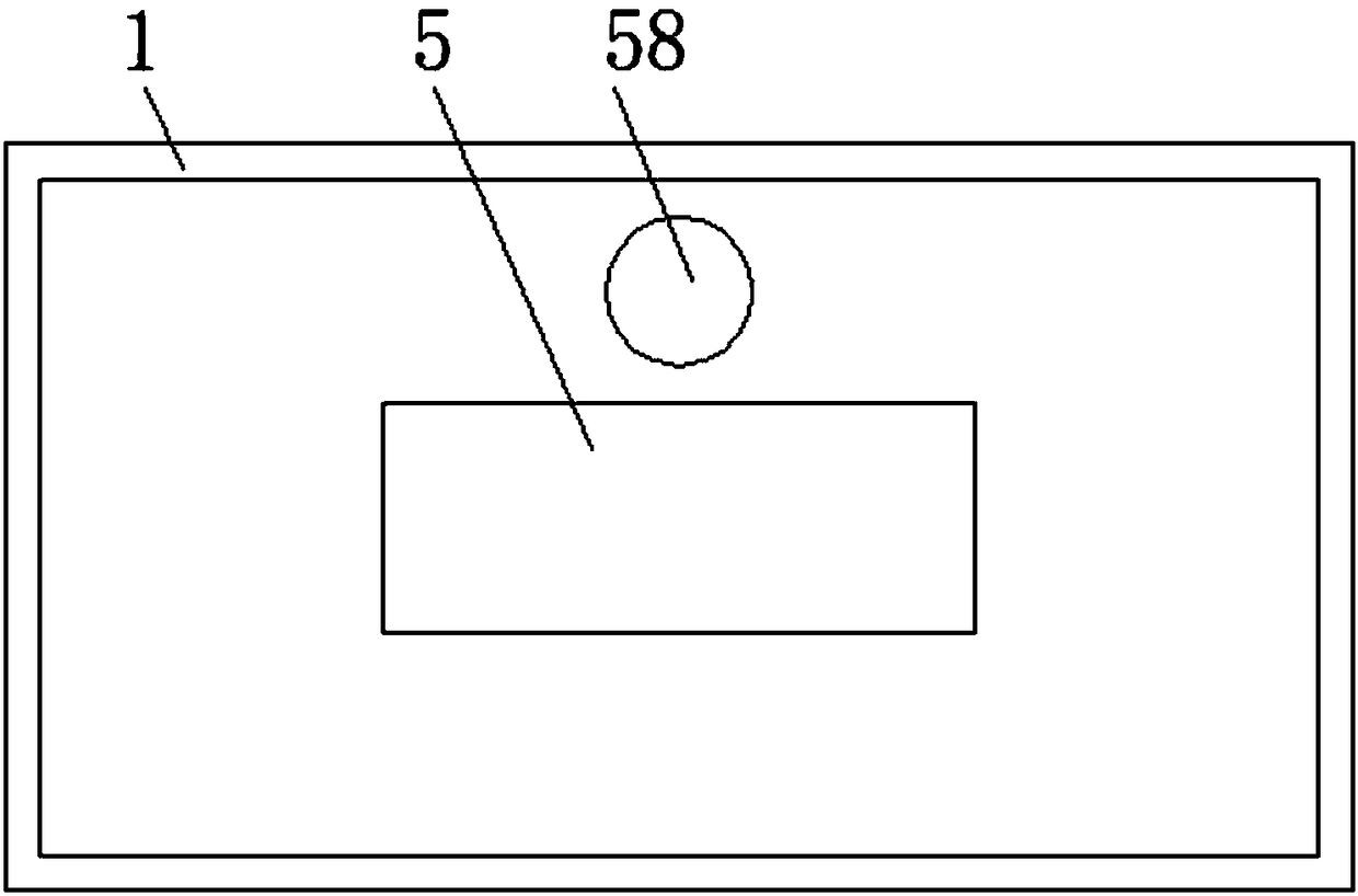
[0028] See Figure 1-5 , An agricultural fertilizer applicator with quantitative fertilization, including a box body 1, a partition plate 2 and a baffle plate 3 are fixedly installed in the middle of the inner cavity of the box body 1, and a side plate 48 is fixedly installed on the right side of the box body 1. A mounting block 53 is fixedly sleeved on the sliding rod 52 between 48. The number of the mounting blocks 53 is two. The front faces of the two mounting blocks 53 are fixedly mounted with push rods 54. The other ends of the two push rods 54 are fixedly connected with The number of the handle 55 and the side plate 48 is two. The middle part of the inner cavity of the two side plates 48 is movably sleeved with a sliding block 49. One side of the two sliding blocks 49 is fixedly installed with a threaded rod 50. One end penetrates the side plate 48, the threaded rod 50 on the outer side of the side plate 48 is threaded with a threaded cap 51, a sliding rod 52 is fixedly installed between the two side plates 48, and both ends of the sliding rod 52 penetrate the side plate 48 and It extends to the inside of the side plate 48 and is fixedly connected with the side of the slider 49. The fertilizer applicator can adjust the height of the handle 55 by adjusting the position of the slider 49, which is convenient for people of different heights to operate the fertilizer applicator and improves the practicability of the fertilizer applicator , A bottom rod 40 is fixedly installed at the middle of the bottom end of the box body 1, the number of bottom rods 40 is three, the inside of the three bottom rods 40 is movably sleeved with a passive plate 41, and the bottom of the passive plate 41 is fixedly installed with a transmission rod 43, The other end of the transmission rod 43 is fixedly connected with a support block 44, and a movable rod 45 is movably sleeved on the support block 44. Both ends of the movable rod 45 are movably sleeved with a runner 46, and the outer edge of the runner 46 is movably sleeved with The crawler belt 47 and the crawler belt 47 increase the passing capacity of the fertilizer applicator on soft and muddy ground, enable the fertilizer applicator to move stably, and improve the stability of the fertilizer applicator. A second compression spring 42 is fixed on the top of the passive plate 41. The other end of the second compression spring 42 is fixedly connected to the top of the inner cavity of the bottom rod 40. The second compression spring 42 provides a shock absorption effect during the movement of the fertilizer applicator, which improves the stability of the fertilizer applicator. The left end of the inner wall of the box 1 A support box 31 is fixedly installed. The inside of the support box 31 is fixedly installed with a dual-axis motor 32. Both output shafts of the dual-axis motor 32 are fixedly installed with side rods 33. The two side rods 33 are far away from the end of the dual-axis motor 32. Both are fixedly sleeved with a rotating drum 34. The dual-axis motor 32 provides power for the soil turning cutter 37 to turn the soil, which improves the rationality of the fertilizer applicator. The left end of the bottom of the box 1 is fixedly installed with a connecting plate 35. The number is two. A passive shaft 36 is movably sleeved between the two connecting plates 35. Both ends of the passive shaft 36 are fixedly sleeved with a rolling wheel 56. The rolling wheel 56 is movably sleeved with a V-belt 38 and a V-belt 38. The other end is movably sleeved with the rotating drum 34. The triangular belt 38 makes the side rod 33 and the soil turning knife 37 rotate in the same direction and at the same speed, which improves the rationality of the fertilizer applicator. The driven shaft 36 is fixedly sleeved with the soil turning knife 37. The number of tilling knives 37 is four. The four tilling knives 37 are equidistantly distributed on the driven shaft 36. The four tilling knives 37 increase the tilling area of the fertilizer applicator and improve the tilling efficiency of the fertilizer applicator. The length of the baffle 3 is less than the length of the baffle 2. The bottom end of the side of the baffle 2 is fixedly installed with a slip screen 4, and the other end of the slip screen 4 is connected to the baffle 3 The bottom end of the side is fixedly connected, the middle of the top of the box body 1 is fixedly installed with a fixed box 5, the top of the box body 1 is provided with a feeding port 58, which is located above the fixed box 5, and the bottom end of the inner cavity of the fixed box 5 is fixed The layered plate 6 is installed, the first motor 7 is fixedly installed on the right side of the top end of the inner cavity of the fixed box 5, the output shaft of the first motor 7 is fixedly installed with a rotating shaft 8, and the other end of the rotating shaft 8 penetrates the layered plate 6, The fixed box 5 and the box body 1 extend to the middle of the inner cavity of the box body 1. The rotating shaft 8 at the bottom of the layered plate 6 is fixedly sleeved with a driving gear 57. The left end of the driving gear 57 is meshed with a driven gear 9, and the driven gear 9 A stirring rod 10 is fixedly sleeved inside. One end of the stirring rod 10 sequentially penetrates the fixed box 5 and the box body 1 and extends to the inner cavity of the box body 1. The rotating shaft 8 and the stirring rod 10 inside the box body 1 are both fixedly sleeved with The stirring blade 11 and the other end of the stirring rod 10 successively penetrate the driven gear 9 and the layered plate 6 and extend to the outside of the top of the layered plate 6, and the limit block 12 is movably sleeved on the stirring rod 10 outside the top of the layered plate 6. A deflector 13 is fixedly installed at the bottom end of the side surface of the partition plate 2, and the other end of the deflector 13 is fixedly connected to the bottom of the inner cavity of the box 1, and the deflector 13 is located below the slip screen 4, on the right side of the inner cavity of the box 1. A protective box 14 is fixedly installed at the top end of the protective box 14. A second motor 15 is fixedly installed inside the protective box 14. A rotating rod 16 is fixedly installed on the output shaft of the second motor 15. The other end of the rotating rod 16 penetrates the protective box 14 and extends to On the outside of the left side of the protective box 14, a disk 17 is fixedly sleeved on the rotating rod 16 on the left side of the protective box 14. The bottom end of the left side of the disk 17 is fixedly installed with a connecting rod 18, and the connecting rod 18 has a movable sleeve Sleeve rod 19, the bottom end of the left side of the sleeve rod 19 is fixedly installed with a passive rod 20, the passive rod 20 is movably sleeved with a pressure rod 21, the other end of the pressure rod 21 is fixedly installed with a non-slip pressing block 22, the other side of the baffle The bottom end of the side is fixedly installed with a fixed rod 23, the other end of the fixed rod 23 is fixedly connected to the right side of the inner wall of the box 1, the fixed rod 23 is movably sleeved with the pressure rod 21, and the bottom end of the right side of the box 1 is fixedly installed with Support rod 24, support rod 24 is movably sleeved with support rod 25, the right end of the bottom of support rod 25 is fixedly installed with upper connecting rod 26, the bottom of upper connecting rod 26 is fixedly connected with first compression spring 27, and the inner cavity of box 1 A lower connecting rod 28 is fixedly installed at the right end of the bottom, the other end of the first compression spring 27 is fixedly connected to the top of the lower connecting rod 28, and the left end of the bearing rod 25 is fixedly connected with a spoiler 29, the spoiler 29 and the baffle 3 Removable connection, the right end of the bottom of the inner cavity of the box 1 is fixedly installed with a limit plate 30. The limit plate 30 is located between the lower connecting rod 28 and the baffle plate 29. The right end of the bottom of the box 1 is fixedly connected with a discharge pipe 39. The material pipe 39 is located below the limiting plate 30.
[0029] When working, first, pour the fertilizer into the box 1 through the feeding port 58, then turn on the first motor 7 to make the mixing blade 11 stir the fertilizer, turn on the dual-shaft motor 32 and the second motor 15, and then the operator, hands Hold the handle 55, push the box 1 through the push rod 54, and use the runner 46 to move the fertilizer applicator. At the same time, the tiller 37 will turn the farmland. The non-slip pressing block 22 will press the bearing rod 25, and the fertilizer will pass out. The feed pipe 39 sends fertilizer to the soil, so that the fertilizer applicator reaches quantitative fertilizer application.
[0030] To sum up, the agricultural fertilizer applicator with quantitative fertilizer application is driven by the rotation of the dual-axis motor 32 to drive the side rod 33 to rotate. The driving cooperation between the drum 34, the V-belt 38 and the rolling wheel 56 is used to rotate the driven shaft 36 At the same time, the turning knife 37 is turned to turn the soil, which is beneficial to the fertilization of the fertilizer applicator and improves the practicability of the fertilizer applicator. The rotation of the first motor 7 drives the rotation shaft 8 and the driving gear 57 to rotate. The driving gear 57 is used. Cooperating with the transmission between the driven gear 9 to make the stirring rod 10 rotate, the rotation of the shaft 8 and the stirring rod 10 drive the stirring blade 11 to rotate, stir the fertilizer in the box 1, and crush the bulk fertilizer into granules. It is beneficial for crops to better absorb chemical fertilizers and improves the practicability of the fertilizer applicator. Through the rotation of the second motor 15, the rotating rod 16 is driven to rotate, and the disc 17 is rotated at the same time. The connecting rod 18, the sleeve rod 19 and the passive rod 20 are used. The transmission cooperation with the pressure rod 21 makes the non-slip pressing block 22 perform intermittent pressing motions on the bearing rod 25, so that the baffle plate 29 intermittently moves up and down to achieve quantitative fertilization of the fertilizer applicator and improve the practicability of the fertilizer applicator; The existing fertilizer applicator has a single function, only has the function of fertilization, and cannot quantify fertilization. If too much fertilizer is applied, it will waste resources and destroy the soil structure. If the fertilizer is too little, it will cause insufficient nutrition of crops and affect the growth of crops. Moreover, since chemical fertilizers are easily damp after being stored for a long time, the damp chemical fertilizers will agglomerate. If the chemical fertilizers are poured directly into the fertilizer applicator, the agglomerated chemical fertilizers will fall into the land, causing a waste of resources. Excessive fertilizers will cause crops. Overnutrition causes crop necrosis and affects crop yield. If fertilizer is directly applied through a fertilizer applicator, the soil is not loosened, which will reduce the problem of soil absorption.
[0031] It should be noted that in this article, relational terms such as first and second are only used to distinguish one entity or operation from another entity or operation, and do not necessarily require or imply one of these entities or operations. There is any such actual relationship or order between. Moreover, the terms "include", "include" or any other variants thereof are intended to cover non-exclusive inclusion, so that a process, method, article or device including a series of elements not only includes those elements, but also includes those that are not explicitly listed Other elements of, or also include elements inherent to this process, method, article or equipment.
[0032] Although the embodiments of the present invention have been shown and described, those of ordinary skill in the art can understand that various changes, modifications, and substitutions can be made to these embodiments without departing from the principle and spirit of the present invention. And variations, the scope of the present invention is defined by the appended claims and their equivalents.