
Automatic screw fastening and laser coding machine

A technology of automatic screw locking and laser coding machine, which is applied in laser welding equipment, manufacturing tools, welding equipment, etc., can solve problems such as low work efficiency, over-twisted teeth, screw twisting, etc., to achieve automatic production and improve Production efficiency, the effect of ensuring accuracy

Pending Publication Date: 2018-06-22
DONGGUAN JISHENG AUTOMATION FACILITIES TECH CO LTD
View PDF0 Cites 3 Cited by
  • Summary
  • Abstract
  • Description
  • Claims
  • Application Information

AI Technical Summary

Problems solved by technology

However, in the industrial production process, most of the screws on the workpiece are manually installed. If workers use manual screwdrivers to install, the efficiency will be relatively low. If workers use electric screwdrivers to install, then the efficiency will be improved to a certain extent. However, the accuracy of the installation of each screw cannot be guaranteed, and the consistency of the installation torque of each screw cannot be guaranteed, and it is easy to cause the screw to be twisted or over-tightened to slip, resulting in damage to the screw or damage to the screw hole of the workpiece or the scrapping of the workpiece
In addition, for most electronic products, after the assembly is completed, each electronic product needs to be tested. Most of the electronic product testing is done manually using testing instruments to test the electronic products one by one, so the work efficiency is very low, and it is also There is no guarantee that the tested products are 100% problem-free

Method used


Image

  • Automatic screw fastening and laser coding machine
  • Automatic screw fastening and laser coding machine
  • Automatic screw fastening and laser coding machine

Examples


Embodiment Construction

[0025] In order to make the object, technical solution and technical effect of the present invention clearer, the present invention will be further described below in conjunction with specific embodiments. It should be understood that the specific embodiments described here are only used to explain the present invention, not to limit the present invention.

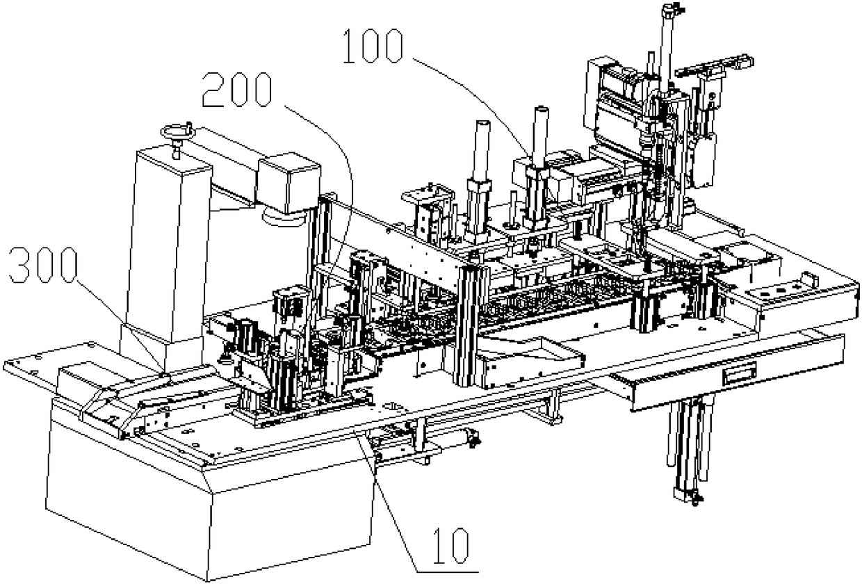
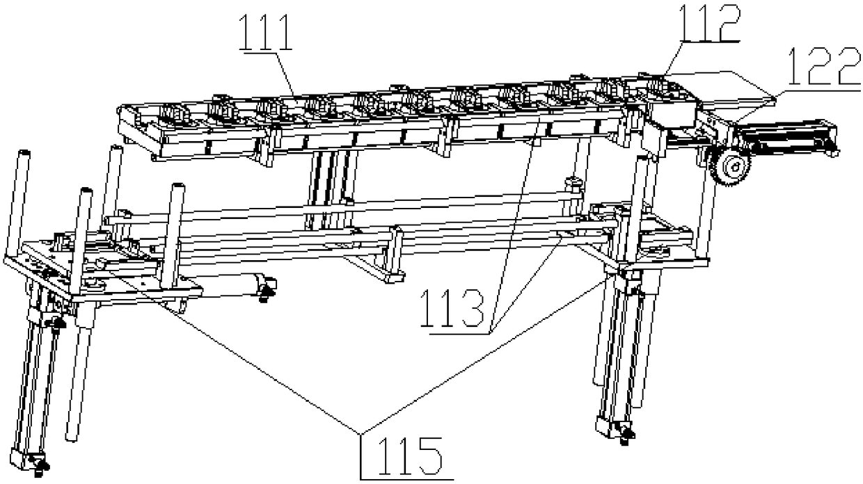
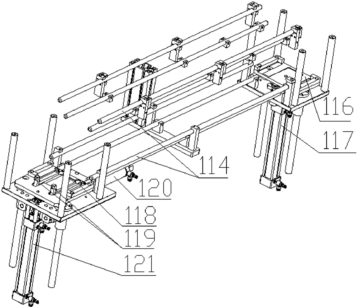
[0026] refer to figure 1 As shown, an automatic locking screw and laser coding machine has a workbench 10; the frame 10 is provided with an automatic locking screw mechanism 100 and an automatic laser coding mechanism 200; the automatic locking screw mechanism 100 includes a Tool conveying mechanism 110, locking screw mechanism 130, detection mechanism 150 and sorting mechanism 160, along the conveying path of said jig conveying mechanism 110, said locking screw mechanism 130, said detecting mechanism 150 and said The sorting mechanism 160, the jig conveying mechanism 110 transports the jig and the workpiece placed on the...


PUM


Abstract

The invention provides an automatic screw fastening and laser coding machine. The automatic screw fastening and laser coding machine is provided with a workbench. The workbench is provided with an automatic screw fastening mechanism and an automatic laser coding mechanism. The automatic screw fastening mechanism comprises a jig conveying mechanism, a screw fastening mechanism body, an inspection mechanism and a sorting mechanism. The screw fastening mechanism body, the inspection mechanism and the sorting mechanism are arranged along the conveying path of the jig conveying mechanism in sequence. The jig conveying mechanism conveys a jig and a workpiece placed on the jig to the screw fastening mechanism for screw fastening, then conveys the jig and the workpiece placed on the jig to the inspection mechanism for workpiece inspection, and goes on to convey the jig and the workpiece placed on the jig to the sorting mechanism, so that defective products are sorted out and sent to a defective product collecting station, and qualified workpieces are sent to the laser coding mechanism for coding. The automatic laser coding mechanism is further arranged on one side of the sorting mechanism.The automatic laser coding mechanism comprises a laser coding machine and a linkage clamping mechanism. Full-automatic machining on products is realized, the production efficiency is greatly improved, and the yield of products is increased.

Description

technical field [0001] The invention relates to the technical field of automatic machinery, in particular to an automatic locking screw and a laser coding machine. Background technique [0002] Screws are indispensable fastening parts in daily life and industrial production, and are widely used in daily life and industrial production; such as electronic products, engineering machinery, furniture products, etc. However, in the industrial production process, most of the screws on the workpiece are manually installed. If workers use manual screwdrivers to install, the efficiency will be relatively low. If workers use electric screwdrivers to install, then the efficiency will be improved to a certain extent. However, the accuracy of the installation of each screw cannot be guaranteed, and the consistency of the installation torque of each screw cannot be guaranteed, and it is easy to cause the screw to be twisted or over-tightened to slip, resulting in damage to the screw or dam...

Claims


Application Information

Patent Timeline
Patent Type & Authority Applications(China)
IPC IPC(8): B23P19/06B23K26/362B23K26/70
CPCB23K26/361B23K26/702B23P19/001B23P19/007B23P19/06Y02P70/50
Inventor 罗超彬朱越照
Owner DONGGUAN JISHENG AUTOMATION FACILITIES TECH CO LTD
Learn More