Machining device for clamping strip in glass slide box for laboratory
A slide box and processing device technology, which is applied in wood processing equipment, manufacturing tools, forming/shaping machines, etc., can solve the problems of troublesome disk cutters, high production costs, and easy return of clipping strips, etc., and achieve reduction High production cost and high versatility
- Summary
- Abstract
- Description
- Claims
- Application Information
AI Technical Summary
Problems solved by technology
Method used
Image
Examples
Embodiment 1
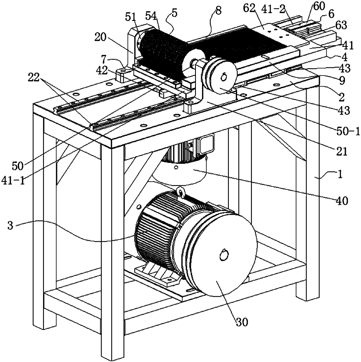
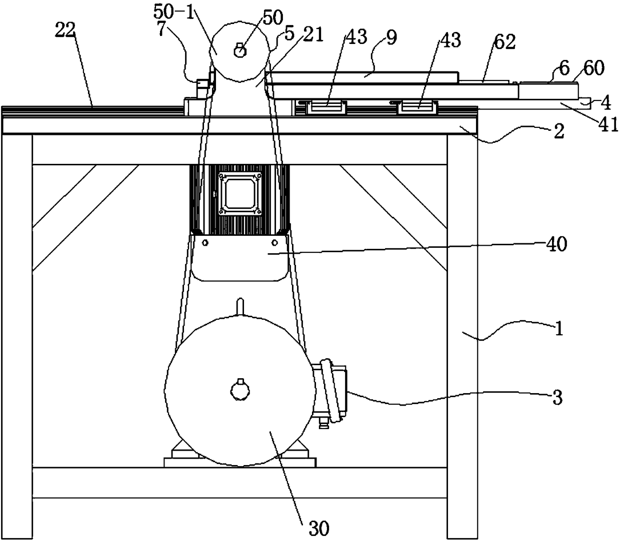
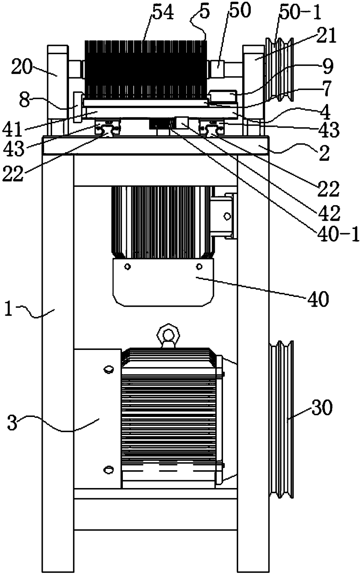
[0033] The laboratory uses a strip processing device in the slide box. Before processing, the wooden strips are manually placed on the ends of the side plate one 8 and the side plate two 9, and the side plate one 8 and the side plate two 9 Push forward with your hand under the guidance of the guide until the wooden strips are full one by one, then start the double piston rod cylinder 60 in the feeding and pressing mechanism 6, and the piston rod of the double piston rod cylinder 60 drives the guide block 61 on the guide rod 63 Under the guiding effect of the guide, the side of the last wooden bar is firmly pressed with the pressing plate 62, which realizes the pressing operation after the loading and avoids the occurrence of the return of the material.
[0034] After the above-mentioned preparations are ready, start the three-phase asynchronous AC motor 3 first, and the three-phase asynchronous AC motor 3 drives the large pulley 30 to rotate with the small pulley 50-1 through t...
Embodiment 2
[0036] This laboratory uses the card strip processing device in the slide box, for slides of different sizes, it is necessary to increase or decrease the number of disc cutters 54 on the main shaft 50, because one end of the knife roller assembly 5 is connected to the first bearing seat 20 Rotationally connected, the other end is rotatably connected with the second bearing seat 21. The cutter roller assembly 5 is composed of a main shaft 50, a bearing top cover flange 51, a rolling bearing 52, a sub-cutter 53 and a disc cutter 54. One end of the main shaft 50 The rolling bearing 52 is connected to the first bearing seat 20 in rotation, and one of the bearing top cover flanges 51 is pressed against the side of the rolling bearing 52 to connect with the first bearing seat 20, and the other end of the main shaft 50 is rotated with the second bearing seat 21 through the rolling bearing 52 connection, and another bearing top cover flange 51 is pressed on the side of the rolling bear...
PUM
 Abstract
Description
Claims
Application Information
 - R&D
- Intellectual Property
- Life Sciences
- Materials
- Tech Scout
- Unparalleled Data Quality
- Higher Quality Content
- 60% Fewer Hallucinations
Browse by: Latest US Patents, China's latest patents, Technical Efficacy Thesaurus, Application Domain, Technology Topic, Popular Technical Reports.
© 2025 PatSnap. All rights reserved.Legal|Privacy policy|Modern Slavery Act Transparency Statement|Sitemap|About US| Contact US: help@patsnap.com


