Car body horizontal conveying mechanism for uphill and downhill

A technology of horizontal conveying and conveying mechanism, which is applied in the direction of motor vehicles, transportation and packaging, etc. It can solve the problems of high use cost, high investment cost, production accidents, etc., and achieve the effect of reducing operating cost, reducing energy consumption, and reducing energy consumption

Inactive Publication Date: 2018-06-22
安徽哈工道一智能制造技术有限公司
View PDF5 Cites 2 Cited by
  • Summary
  • Abstract
  • Description
  • Claims
  • Application Information

AI Technical Summary

Problems solved by technology

In the existing technology, pneumatic drive control is usually used to realize vertical up and down transportation, which has high efficiency; but the investment cost is high, the energy consumption is large, and the use cost is high
In the prior art, up and down slopes are also used to realize up and down transportation, which can realize various transportation requirements of the vehicle body spreader in the horizontal direction or in the uphill and downhill direction only through the transportation track; however, the vehicle body spreader and the production line track often use Two-point connection, its track is parallel to the track of the production line. If there are no other measures, the body will shake or tilt forward when going uphill or downhill, which will easily cause the body to detach, cause production accidents, and cause economic losses.

Method used


Image

  • Car body horizontal conveying mechanism for uphill and downhill
  • Car body horizontal conveying mechanism for uphill and downhill
  • Car body horizontal conveying mechanism for uphill and downhill

Examples


Embodiment Construction

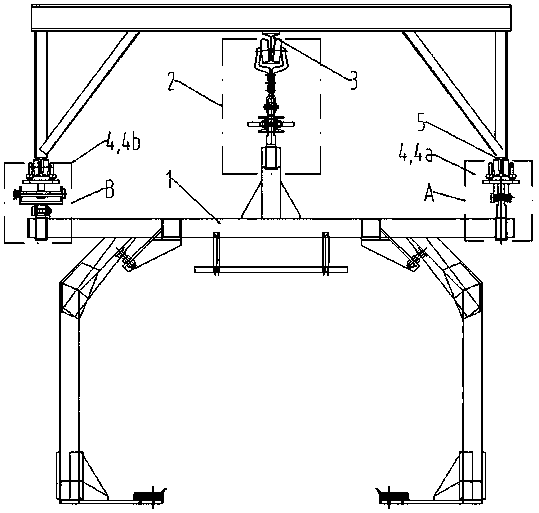
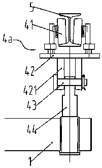
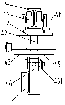
[0024] refer to Figure 1 to Figure 7 , the structural features of the uphill and downhill vehicle body level conveying mechanism are described in detail as follows:

[0025] A horizontal conveying mechanism for up and downhill vehicle bodies, which includes a vehicle body spreader 1, a main sprocket mechanism 2 and a main sprocket track 3; the main sprocket mechanism 2 is fixed at one end of the top of the vehicle body spreader 1, and the main sprocket The sprocket mechanism 2 is slidingly connected to the main sprocket track 3; the conveying mechanism also includes a horizontal auxiliary mechanism 4 located at the other end of the top of the vehicle body hanger 1, and the horizontal auxiliary mechanism 4 includes a pulley 41, a support frame 42, a connecting shaft 43 and Fixing frame 44, described pulley 41 is located at support frame 42 inner sides, and described support frame 42 bottoms are vertically fixed with connecting plate 421, and described connecting plate 421 and ...


PUM


Abstract

The invention discloses a car body horizontal conveying mechanism for uphill and downhill. The car body horizontal conveying mechanism comprises a car body lifting device, a main chain wheel mechanismand a main chain wheel track; the main chain wheel mechanism is fixedly arranged at one end of the top of the car body lifting device, and the main chain wheel mechanism is slidably connected with the main chain wheel track; the car body horizontal conveying mechanism further comprises horizontal auxiliary mechanisms disposed at the other end of the top of the car body lifting device, and the horizontal auxiliary mechanisms comprise pulleys, support frames, connecting shafts and fixing frames; the pulleys are disposed on the inner sides of the support frames, and the bottom ends of the support frames are vertically and fixedly provided with connecting plates; the connecting plates and the fixing frames are hinged with the connecting shafts; the fixing frames are fixedly disposed on the top of the car body lifting device; and the car body horizontal conveying mechanism further comprises auxiliary tracks disposed directly above the horizontal auxiliary mechanisms, and the pulleys slidewithin the auxiliary tracks. The car body horizontal conveying mechanism for the uphill and the downhill is simple in structure and convenient to manufacture; and it is ensured that the car body lifting device is always in a horizontal state, the energy consumption is reduced, the cost of use is reduced, the economic expenses are saved, and the popularization and application are facilitated.

Description

technical field [0001] The invention relates to a vehicle body conveying mechanism, in particular to an uphill and downhill vehicle body horizontal conveying mechanism. Background technique [0002] At present, in the production process of automobiles, it is often necessary to lift the whole vehicle to different process parts on the production line by means of a spreader, or lift it to other equipment for processing or to install other components. In the process of automobile assembly, there are situations that need to be transported up and down. In the prior art, pneumatic drive control is usually used to realize vertical up and down transportation, which has high efficiency; however, the investment cost is high, the energy consumption is large, and the use cost is high. In the prior art, up and down slopes are also used to realize up and down transportation, which can realize various transportation requirements of the vehicle body spreader in the horizontal direction or i...

Claims


Application Information

Patent Timeline
Patent Type & Authority Applications(China)
IPC IPC(8): B62D65/18
CPCB62D65/18
Inventor 吴成龙孙正锐张远
Owner 安徽哈工道一智能制造技术有限公司
Why Eureka
Try Eureka