Al technical title is built by PatSnap Al team. It summarizes the technical point description of the patent document.
A construction equipment and electric power technology, applied in the electric power field, can solve the problems of high labor intensity, long time consumption, cumbersome and complicated process, etc., and achieve the effect of reducing labor intensity, improving work efficiency and ensuring personnel safety.
Inactive Publication Date: 2018-06-22
李猛
View PDF0 Cites 6 Cited by
Summary
Abstract
Description
Claims
Application Information
AI Technical Summary
This helps you quickly interpret patents by identifying the three key elements:
Problems solved by technology
Method used
Benefits of technology
Problems solved by technology
[0003] In order to solve the above problems, the present invention provides a kind of electric power intelligent construction equipment, which can solve the need to manually put the cable marker pile into the pit in the existing installation process of the cable marker pile. The process is cumbersome and complicated, and the cable marker pile is moved to the pit. When people carry heavy objects for a long time, their waists are prone to injury and cause potential safety hazards. During the handling process, the cable markers may fall to the ground due to improper handling by personnel. During installation, manual installation cannot ensure that the cable markers are installed vertically in the pit. Due to errors in manual installation, the cable marker pile and the ground cannot be kept level, the process takes a long time, the labor intensity is high and the efficiency is low. It can realize the function of fixing the limit and installation of the cable marker pile, and fix the cable marker pile multiple times. Position limit, automatic azimuth adjustment to ensure that the cable marker pile is installed vertically in the pit, and the cable marker pile is kept level with the ground, without manual operation, ensuring the safety of personnel, short time-consuming, and has the advantages of simple operation, low labor intensity and high work efficiency.
Method used
Image
Click on the blue label to locate the original text in one second.
Reading with bidirectional positioning of images and text.
Examples
Embodiment Construction
[0027] In order to make the technical means, creative features, goals and effects achieved by the present invention easy to understand, the present invention will be further described below in conjunction with specific illustrations. It should be noted that, in the case of no conflict, the embodiments in the present application and the features in the embodiments can be combined with each other.
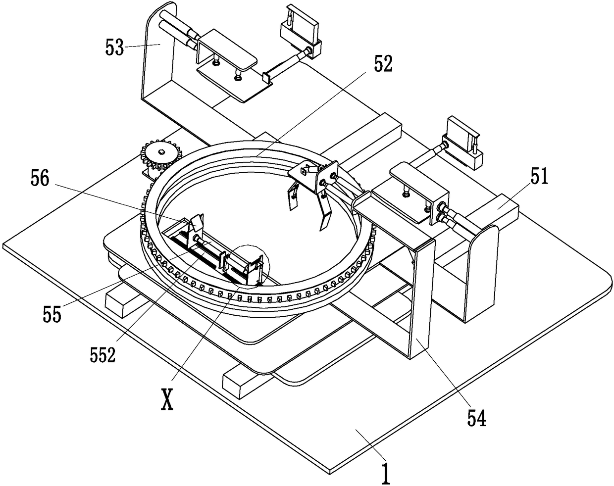
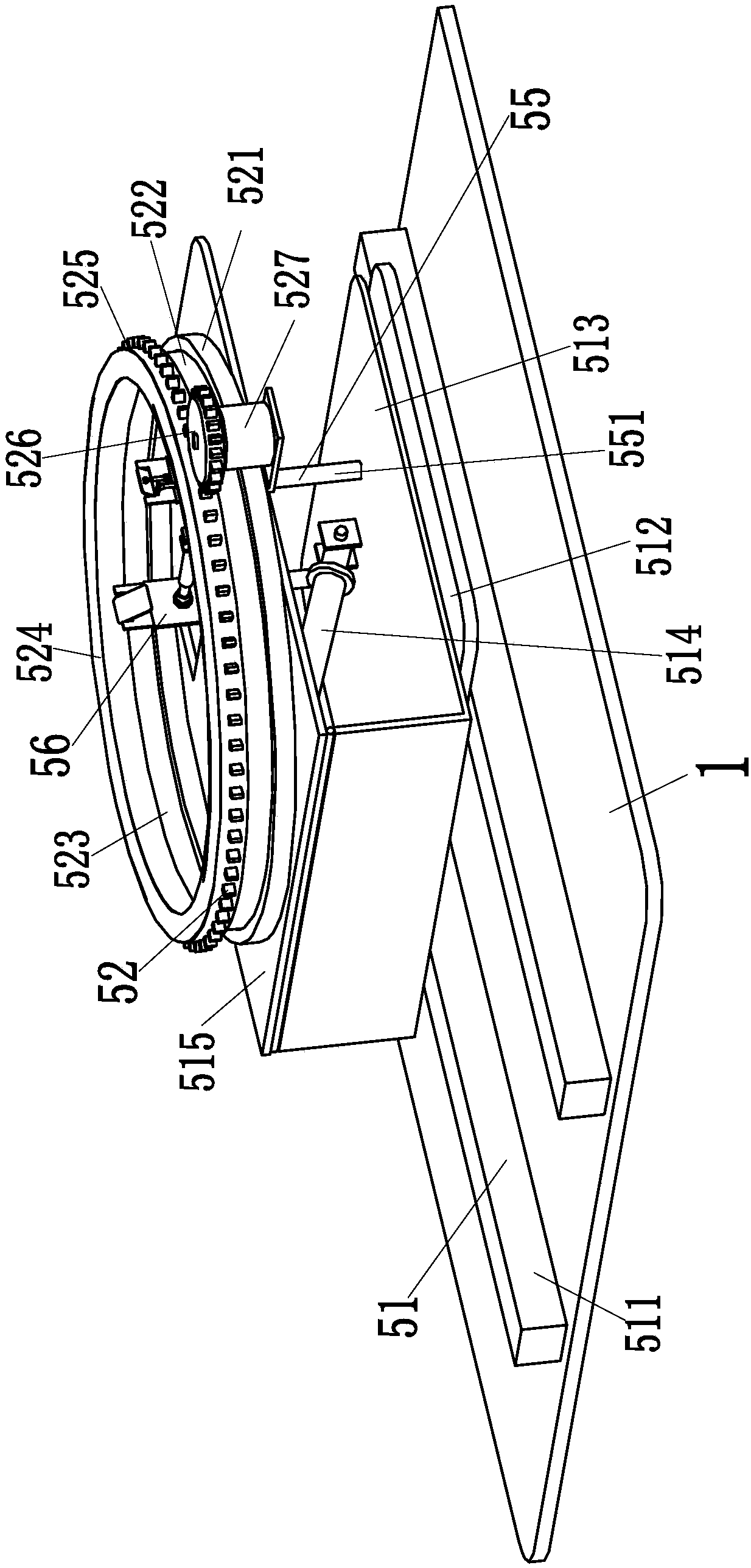
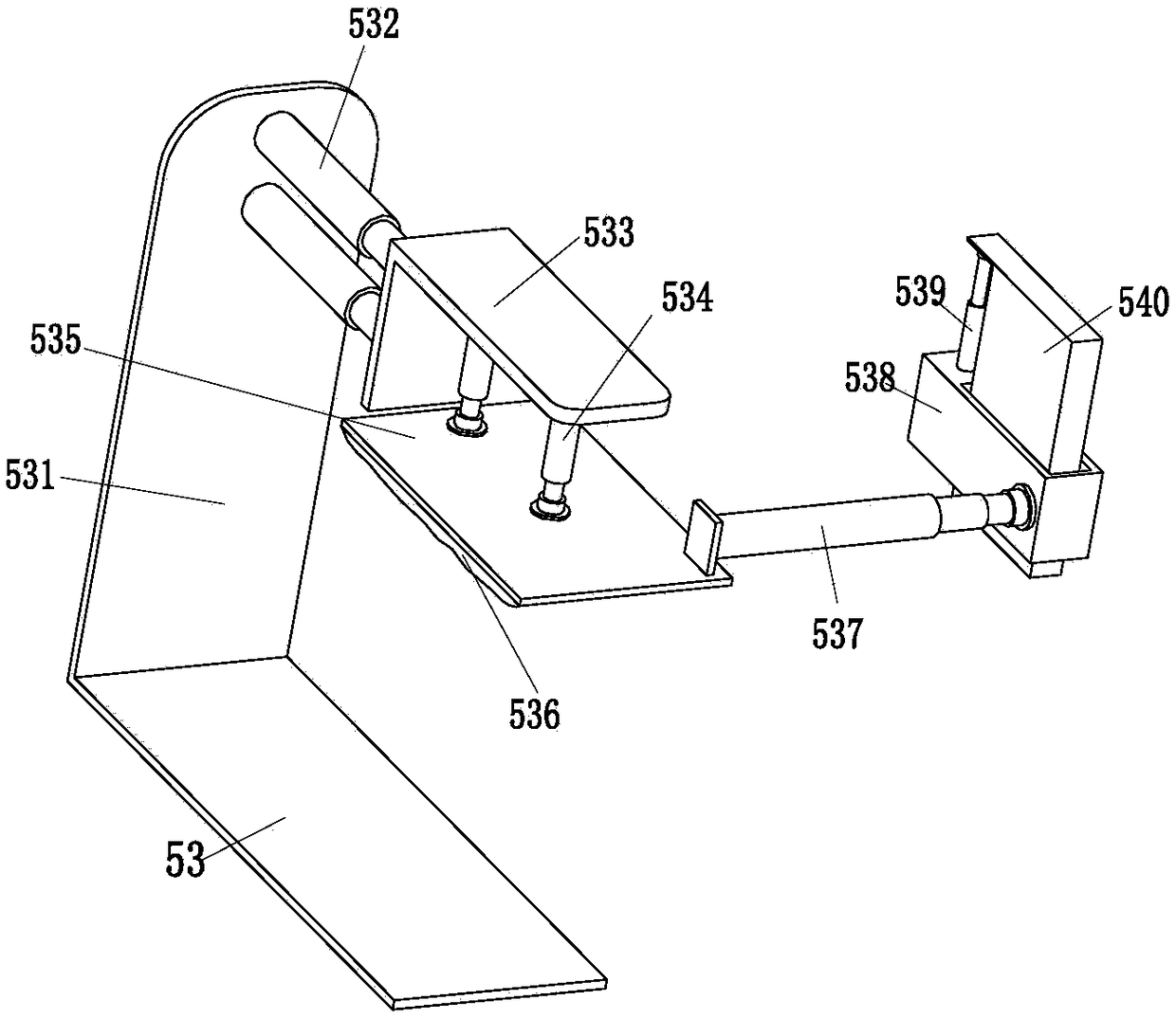
[0028] Such as Figure 1 to Figure 5 As shown, in order to achieve the above purpose, the present invention adopts the following technical solutions: a kind of electric power intelligent construction equipment, including a main board 1, an adjusting mechanism 51, a rotating mechanism 52, two pressing mechanisms 53, an auxiliary clamping mechanism 54, a bottom mechanism 55 and Two fixing mechanisms 56, the rotating mechanism 52 rotate the cable marker pile to a suitable position, the two pressing mechanisms 53 and the auxiliary clip mechanism 54 cooperate to limit the conveyed cable m...
PUM
Abstract
The invention relates to electrical intelligent construction equipment. The electrical intelligent construction equipment comprises a main plate, an adjusting mechanism, a rotating mechanism, two pressing mechanisms, an auxiliary clamping mechanism, a bottom mechanism and two fixing mechanisms; the adjusting mechanism is installed on the main plate; the rotating mechanism is installed at the upperend of the adjusting mechanism; the two pressing mechanisms are installed at the rear end of the adjusting mechanism; the auxiliary clamping mechanism is installed at the right side of the middle part of the adjusting mechanism; the bottom mechanism is installed at the front end of the adjusting mechanism; and the two fixing mechanisms are installed at the upper end of the bottom mechanism and are symmetrically arranged. The electrical intelligent construction equipment provided by the invention can solve the problems that a cable marker post needs to be manually arranged in a soil pit in anexisting cable marker post installation process, the cable marker post may drop to the ground due to improper operation of a person in a transfer process, manual installation cannot guarantee that thecable marker post is vertically installed inside the soil pit in an installation process and the like, and can realize the functions of fixing, limiting and installing the cable marker post.
Description
technical field [0001] The invention relates to the field of electric power, in particular to an electric power intelligent construction equipment. Background technique [0002] Cable marker stakes are also known as power cable marker stakes, marker stakes, natural gas marker stakes channel vertical marker stakes, commonly used in electric power, communication, gas, tap water, railway geographical pipeline path channel indication signs and warning signs, used in downtown, scenic spots , green belts, bushes, pipeline path indication on both sides of pipe jacking, high strength, the product is made of new unsaturated resin material, pressed at high temperature, impact resistance, wear resistance, high temperature resistance, corrosion resistance, so the service life is long 30 years, the appearance is beautiful, the product can be made into various colors, the font pattern is clear, the warning is obvious, and it can beautify the urban environment and prevent theft. This synth...
Claims
Application Information
Patent Timeline
Application Date:The date an application was filed.
Publication Date:The date a patent or application was officially published.
First Publication Date:The earliest publication date of a patent with the same application number.
Issue Date:Publication date of the patent grant document.
PCT Entry Date:The Entry date of PCT National Phase.
Estimated Expiry Date:The statutory expiry date of a patent right according to the Patent Law, and it is the longest term of protection that the patent right can achieve without the termination of the patent right due to other reasons(Term extension factor has been taken into account ).
Invalid Date:Actual expiry date is based on effective date or publication date of legal transaction data of invalid patent.