Step stair and step plates applied to same

A technology for treads and stairs, applied in the direction of treads, stairs, treads and riser units, etc., can solve the problems of long processing time, waste of materials, damage to the surface, etc., achieve good waterproof function, firm structural connection, and increase safety Effect

Inactive Publication Date: 2018-06-22
株洲因奈斯精密刀具有限公司
View PDF4 Cites 0 Cited by
  • Summary
  • Abstract
  • Description
  • Claims
  • Application Information

AI Technical Summary

Problems solved by technology

[0002] At present, stair decoration materials are the most basic part of decoration. The decoration materials on the market must be processed by processing factories. The processing technology is rough and the processing time is long, which will destroy the original texture and luster of the surface of the product, and the quality cannot be guaranteed. , and the materials must be processed according to the existing tile specifications and sizes, resulting in waste of materials, labor, water and electricity
[0003] The disadvantages of the processed products for stairs in the prior art are that they are irregular, not smooth, damage the surface, are not environmentally friendly (glue is used for bonding, and the sticky water itself contains formaldehyde), the surface is grooved to hide dirt, and it is not easy to take care of. Causes waste of materials, processing causes labor, waste of water and electricity, and also brings environmental pollution (water and voice)
[0004] Although factory-produced prefabricated stairs have appeared recently, the tread surface of these prefabricated stairs is smooth. If it is rained outdoors or washed indoors, water will easily remain on the treads, which is not only difficult to clean, but may also bring safety hazards.

Method used


Image

  • Step stair and step plates applied to same
  • Step stair and step plates applied to same
  • Step stair and step plates applied to same

Examples


Embodiment Construction

[0020] In order to make the content of the present invention more clearly understood, the present invention will be further described in detail below based on specific embodiments and in conjunction with the accompanying drawings.

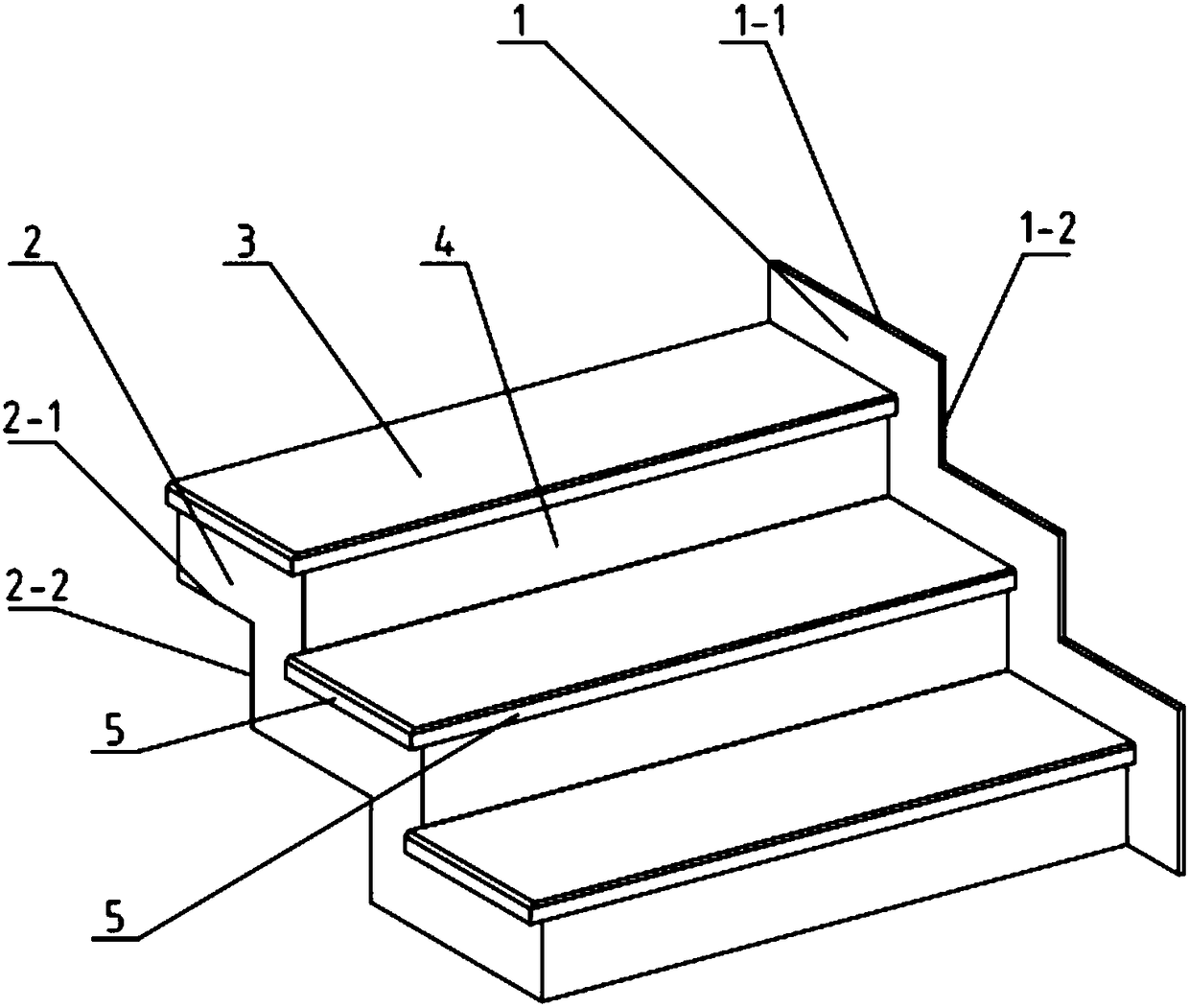
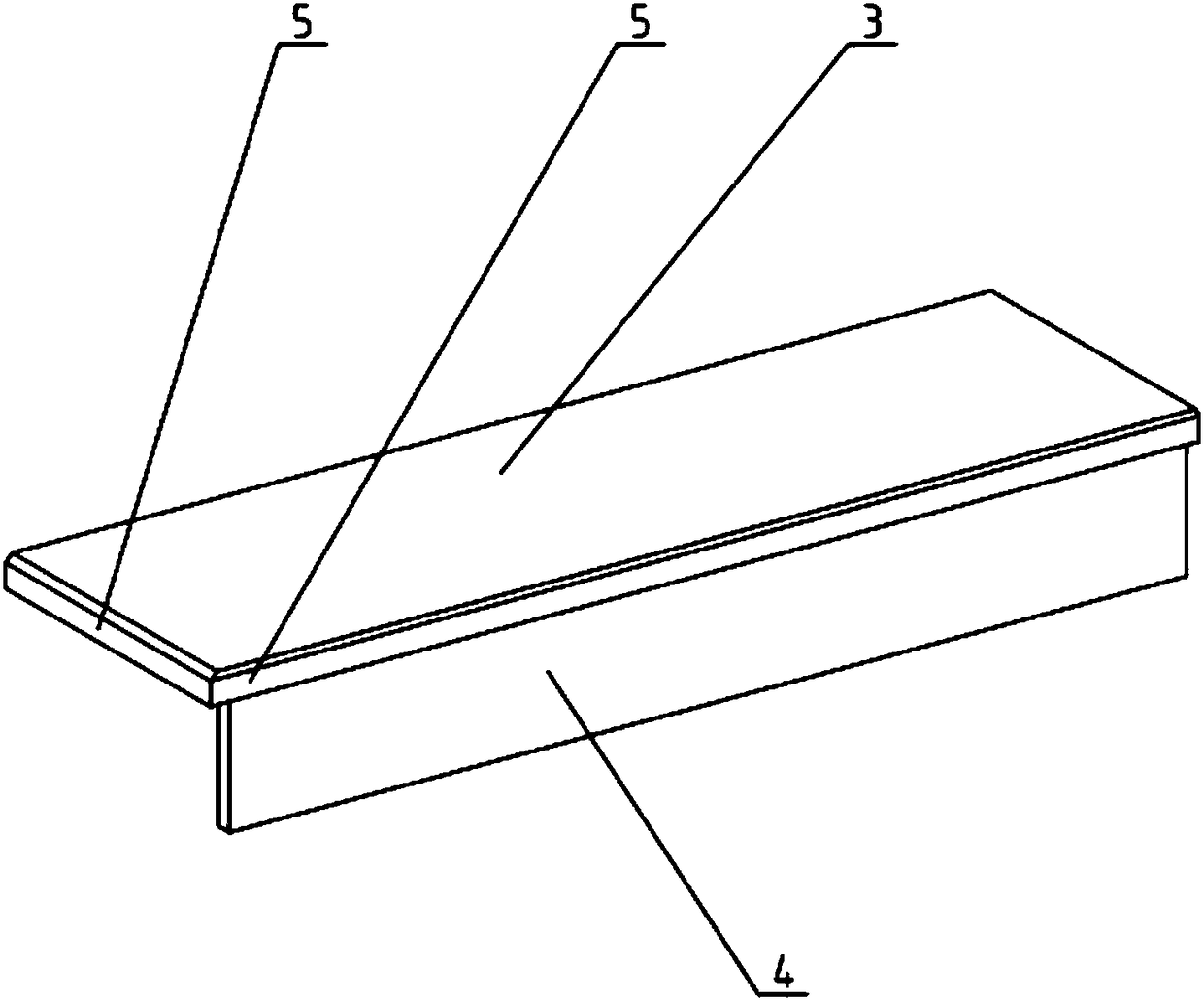
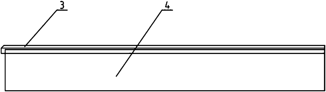
[0021] Such as Figure 1~4 Shown, a kind of stepping staircase, it comprises upper water retaining plate 1, lower water retaining plate 2 and multi-stage tread plate, tread plate comprises step main plate 3 and step side plate 4, one end of step main plate 3 in each step plate Splicing connection with one end of the step side plate 4 without bonding, the other end of the step side plate 4 is spliced ​​with the step main board 3 in the adjacent step plate, the upper water retaining plate 1 and the lower water retaining plate 2 are respectively located on both sides of the multi-stage step board. The connection between the upper water retaining plate 1 and the lower water retaining plate 2 is not bonded, but directly connected by splicing, and the up...


PUM


Abstract

The invention discloses a step stair and step plates applied to the same. The step stair comprises upper water stopping plates, lower water stopping plates and a plurality of step plates, each step plate comprises a step main plate body and a step side plate body, one end of the step main plate body in each step plate is connected with one end of the corresponding step side plate body in a splicing mode, the other end of each step side plate body is connected with the step main plate body of the corresponding adjacent step plate in a splicing mode, the upper water stopping plates and the lowerwater stopping plates are located on the two sides of the multiple step plates correspondingly, the upper edges of the upper water stopping plates sequentially extend outwards out of the multiple step plates, the ends, fixedly connected with the step side plate bodies, of the step main plate bodies extend out of the step side plate bodies, and water dropping lines are arranged on the out extending parts of the step main plate bodies. The side walls, connected with the lower water stopping plates, of the step main plate bodies extend out of the step side plate bodies as well, and water dropping lines are arranged on the out extending parts of the step main plate bodies as well. The step plates have good waterproof functions, the structure is simple and firm, processing is not needed, a binding agent is not required, original textures and glossiness of the product are not damaged in the paving process, the energy source is saved, and a slip prevention function is further achieved.

Description

technical field [0001] The invention relates to a step staircase and a tread plate used therein, belonging to the technical field of stairs. Background technique [0002] At present, stair decoration materials are the most basic part of decoration. The decoration materials on the market must be processed by processing factories. The processing technology is rough and the processing time is long, which will destroy the original texture and luster of the surface of the product, and the quality cannot be guaranteed. , and the materials must be processed according to the existing tile specifications and sizes, resulting in waste of materials, labor, water and electricity. [0003] The disadvantages of the processed products for stairs in the prior art are that they are irregular, not smooth, damage the surface, are not environmentally friendly (glue is used for bonding, and the sticky water itself contains formaldehyde), the surface is grooved to hide dirt, and it is not easy to...

Claims


Application Information

Patent Timeline
IPC IPC(8): E04F11/09E04F11/17
CPCE04F11/09E04F11/17
Inventor 马晓魁
Owner 株洲因奈斯精密刀具有限公司
Why Eureka
Try Eureka