Material stirring and feeding device for chemical production

A technology for chemical production and materials, which is applied to the field of material stirring and unloading devices for chemical production, can solve the problems of waste of plastic particles and labor consumption, and achieve the effect of improving utilization rate and rapid operation.

Inactive Publication Date: 2021-03-09
ZHONGSHAN DONGWANGYANG CHEM
View PDF0 Cites 0 Cited by
  • Summary
  • Abstract
  • Description
  • Claims
  • Application Information

AI Technical Summary

Problems solved by technology

[0005] The purpose of the present invention is to provide a material stirring and unloading device for chemical production in order to overcome the disadvantages of manual dumping of plastic granules that consumes manpower, and that manual dumping of plastic granules is easy to cause waste of plastic granules

Method used


Image

  • Material stirring and feeding device for chemical production
  • Material stirring and feeding device for chemical production
  • Material stirring and feeding device for chemical production

Examples


Embodiment 1

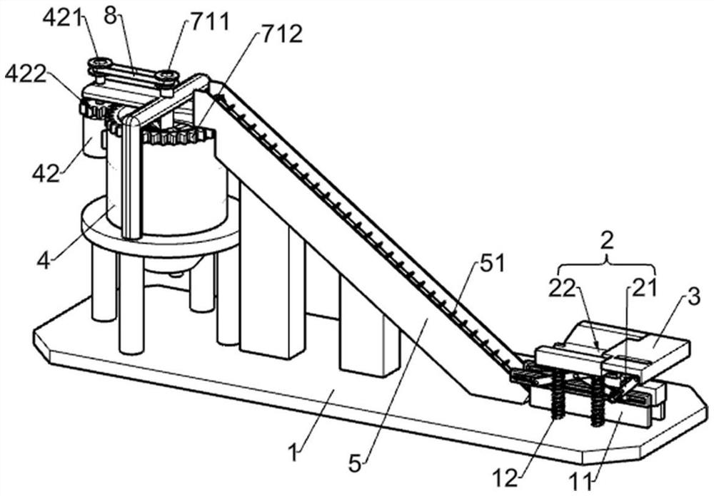
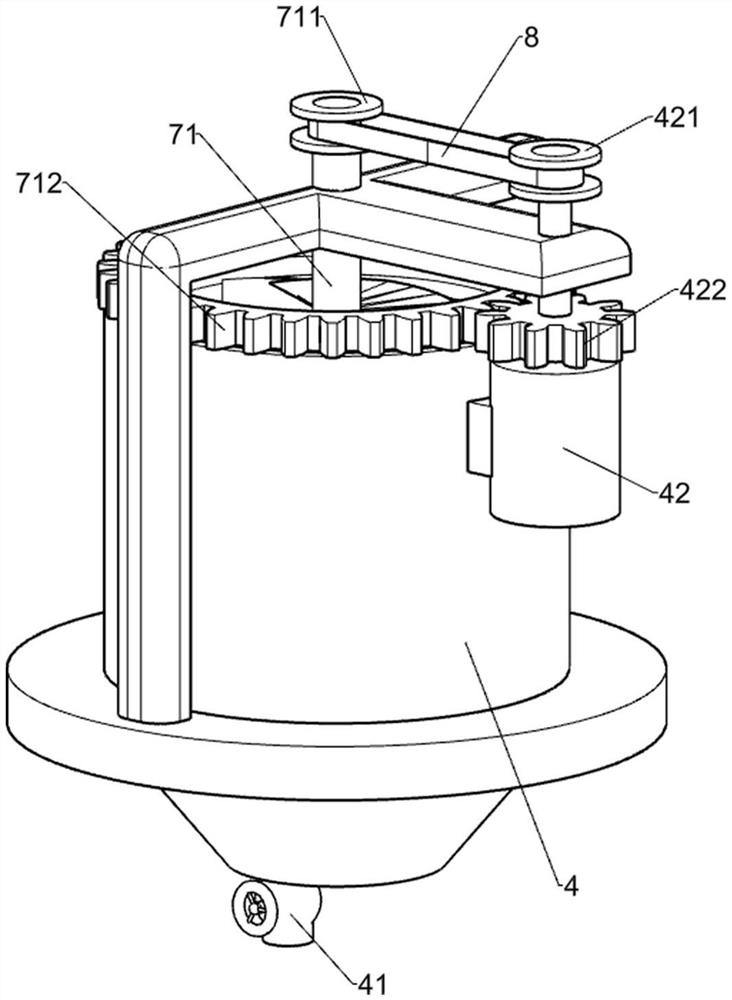
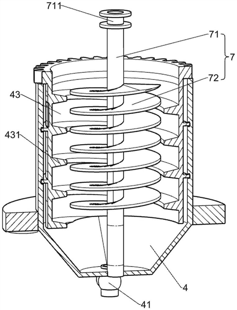
[0027] A chemical production material mixing and feeding device, such as Figure 1-4 As shown, it includes a base 1, a plurality of support blocks 11 fixedly arranged on the base 1, and a mixing bucket 4 fixedly arranged on the base 1. The support blocks 11 are set to two, and adjacent support blocks 11 are arranged in parallel. The support block 11 is fixedly provided with a blanking mechanism 2 for cutting plastic granule packaging bags. The blanking mechanism 2 includes a moving assembly 21 and a cutting assembly 22. An inclined downward slideway 13 is fixedly provided between adjacent support blocks 11. The length direction of slideway 13 is arranged along the length direction of support block 11, and base 1 is provided with conveyer belt 5, and conveyer belt 5 is arranged obliquely upwards along the direction away from support block 11, and conveyer belt 5 is positioned between mixing bucket 4 and slideway 13, and conveyer belt 5 The output end is located directly above t...

Embodiment 2

[0030] On the basis of Example 1, such as Figure 4-7 As shown, the motion assembly 21 includes a plurality of first connecting rods 211, second connecting rods 212, first sliding rails 213 and second sliding rails 214, the first connecting rods 211, the second connecting rods 212, the first sliding rails 213 and the second slide rail 214 are both set to two, the adjacent first slide rail 213 is arranged in parallel, the first slide rail 213 is horizontally set, the first slide rail 213 is fixedly connected with the support block 11, the length of the first slide rail 213 The direction is set along the length direction of the support block 11, and the first sliding groove 2131 is opened on the first sliding rail 213, and the first sliding groove 2131 is opened along the length direction of the first sliding rail 213, and the first connecting rod 211 and the second connecting rod 212 The intersection of the first connecting rod 211 and the second connecting rod 212 is hingedly ...

Embodiment 3

[0033] On the basis of Example 2, such as Figure 5-7 As shown, the cutting assembly 22 includes a slider 221, a fixed block 222 and a cutter 223. The slider 221 is located on the lower surface of the frame 3 and the two are slidably connected. A connecting rod is connected between the slider 221 and the third connecting rod 33. 6. One end of the connecting rod 6 is fixedly connected with the slider 221, the other end of the connecting rod 6 is hinged with the third connecting rod 33, the fixed block 222 is fixedly connected with the slider 221, the fixed block 222 is located on the left side of the slider 221, and the fixed The block 222 is flush with the upper surface of the slider 221. The fixed block 222 is provided with a receiving groove 2221. The cutting knife 223 is located in the receiving groove 2221. The cutting knife 223 is hinged with the two sides of the receiving groove 2221. A plurality of springs are fixedly arranged between the bottom walls of the receiving g...


PUM


Abstract

A material stirring and feeding device for chemical production comprises a base, supporting blocks, a sliding way and the like. The adjacent supporting blocks are arranged in parallel; a feeding mechanism used for cutting plastic particle packaging bags is fixedly arranged on the adjacent supporting blocks; the sliding way inclining downwards is fixedly arranged between the adjacent supporting blocks; a conveying belt is arranged on the base; the conveying belt is arranged obliquely upwards in the direction away from the supporting blocks; and the conveying belt is located between a stirring barrel and the sliding way. The feeding mechanism has the effects that a worker places bagged plastic particles on a rack, a cutting assembly cuts packaging bags of the bagged plastic particles, manpower is saved, rapidness is achieved, operation is easy and convenient, and the plastic particles are not prone to spilling.

Description

technical field [0001] The invention relates to the technical field of stirring equipment, in particular to a material stirring and discharging device for chemical production. Background technique [0002] Plastic particles are ubiquitous in life and play a huge role. Plastic particles are commonly used in daily life to make toys, furniture, stationery and other daily necessities. The processing of plastic particles is divided into many processes, such as cutting of plastic particles, plastic particles Stirring and coloring of plastic particles, etc. Among them, the mixing of plastic particles is generally carried out in a mixer. [0003] In the related art, before the plastic granules are mixed, the packaging bags containing the plastic granules are generally cut manually, and then the plastic granules are poured into the mixer. The manual dumping of the plastic granules is labor-intensive, and it is easy to pour the plastic granules manually. Make the plastic granules po...

Claims


Application Information

Patent Timeline
Patent Type & Authority Applications(China)
IPC IPC(8): B29B7/24B29B7/14B29B7/22B65B69/00
CPCB29B7/14B29B7/22B29B7/24B65B69/0008B65B69/0033
Inventor 苏祖芹
Owner ZHONGSHAN DONGWANGYANG CHEM
Why Eureka
Try Eureka