
Tunnel structure having power generation function

A tunnel and structure technology, which is applied in mine/tunnel ventilation, engine components, machines/engines, etc., can solve the problems of increased engineering volume, increased tunnel section size, and high cost

Pending Publication Date: 2018-06-22
SICHUAN DEPT OF TRANSPORTATION HIGHWAY PLANNING PROSPECTING & DESIGN RES INST
View PDF23 Cites 0 Cited by
  • Summary
  • Abstract
  • Description
  • Claims
  • Application Information

AI Technical Summary

Problems solved by technology

[0005] 1. Since the wind force in the tunnel is not constant, its power generation is not stable, and in order to obtain a stable power supply, it is necessary to install a large battery pack and other energy storage devices, which is extremely costly
[0006] 2. The wind power generation device is installed on the inner wall of the tunnel and occupies the clear space of the tunnel. In order to improve its power generation capacity, it is usually necessary to install auxiliary devices such as wind collecting boxes. Therefore, in order to ensure the clear space in the tunnel, ensure that its vehicles pass through and meet relevant technical specifications Requirements, the size of the tunnel section needs to be increased, resulting in a significant increase in the amount of engineering

Method used


Image

  • Tunnel structure having power generation function
  • Tunnel structure having power generation function
  • Tunnel structure having power generation function

Examples


Embodiment Construction

[0032] Below in conjunction with accompanying drawing and embodiment the present invention is described further as follows:

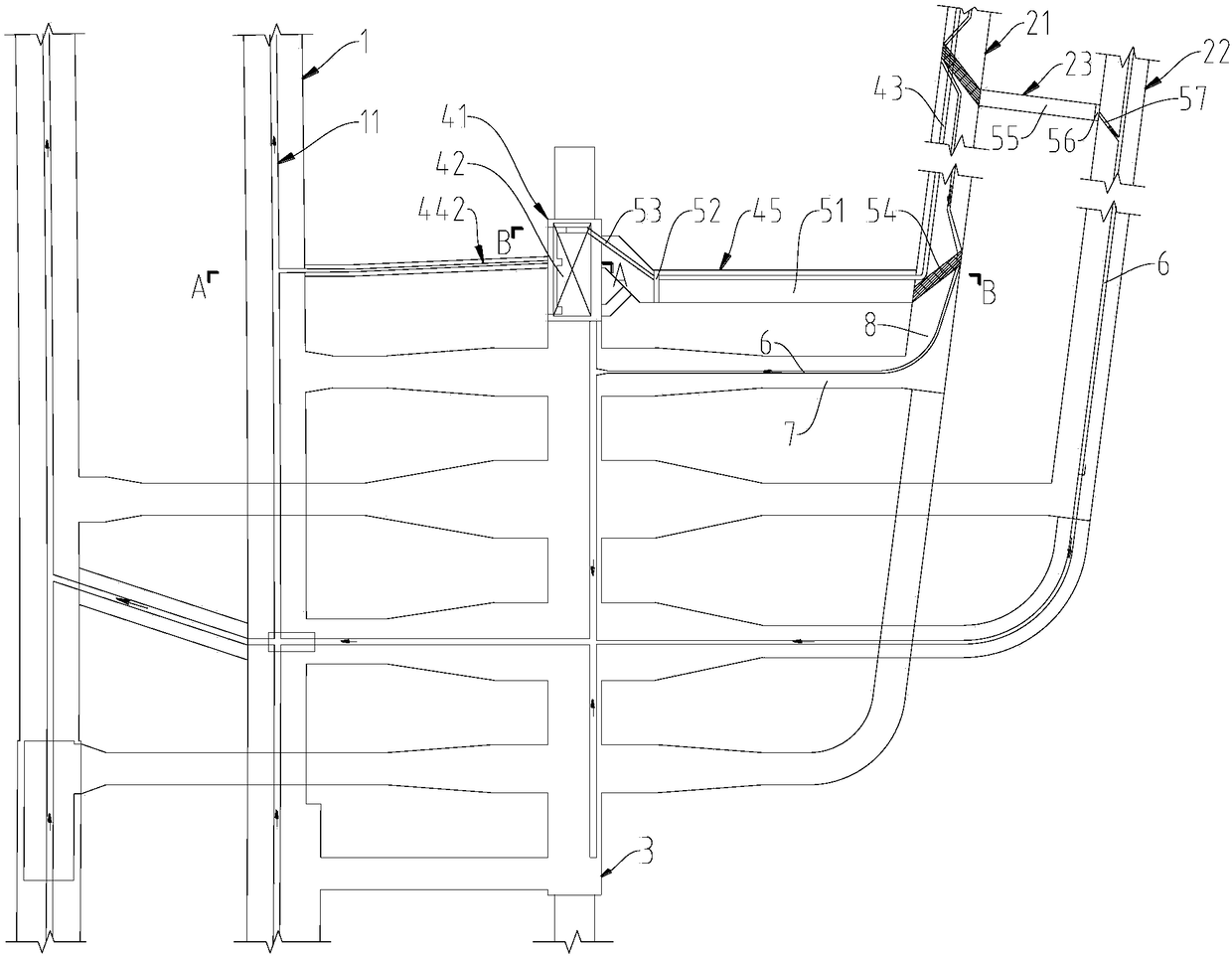
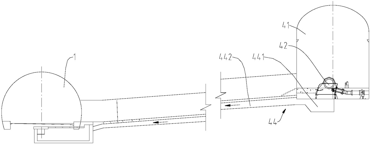
[0033] Such as figure 1 , figure 2 and image 3 As shown, the tunnel structure with power generation function includes a drainage system, a ventilation channel and a power generation system. The ventilation channel is a ventilation shaft and is formed by a vertical shaft or an inclined shaft. The ventilation channel includes an air supply channel and an exhaust channel; The power generation system is a hydroelectric power generation system, which includes a generator room 41 located adjacent to the end of the ventilation shaft, power generation equipment 42 installed in the generator room 41, water diversion pipes 43 for delivering water to the power generation equipment 42, and tail water for discharging power generation tail water. Water channel 44; the water diversion pipe 43 is laid in the ventilation shaft, which extends from the outside of the ...


PUM


Abstract

The invention discloses a tunnel structure having a power generation function, belongs to the field of tunnel structures and aims to lower impact on structures of tunnels themselves and reduce engineering quantity. The tunnel structure comprises a ventilation shaft of a vertical shaft or an inclined shaft and a hydraulic power generation system, the power generation system comprises a power generator room positioned adjacent to the bottom end of the ventilation shaft, power generation equipment mounted in the power generator room, a water diversion pipeline for supplying water to the power generation equipment and a tail water passage, the water diversion pipeline is laid in the ventilation shaft, extends to the power generator room through the ventilation shaft from the outside of a tunnel and is connected with the power generation equipment. A pressure pipeline is paved in the ventilation shaft, so that stability of power generation is ensured; existing structure of the tunnel is utilized, so that additional digging of a ditch for paving the pressure pipeline is not needed, a whole power generation system is enabled to utilize the existing structure of the tunnel as much as possibly, impact of setup of the power generation system on the tunnel structure is lowered to greatest extent, construction difficulty is lowered, and workload is reduced.

Description

technical field [0001] The invention belongs to the field of tunnel structure, in particular to a tunnel structure with power generation function. Background technique [0002] In recent years, as highway construction has extended from plains, hills and low mountainous areas to middle-high mountainous areas, the special terrain and geological conditions of middle-high mountainous areas have resulted in a significant increase in the length of individual tunnels and the total size of tunnels, and there are more and more ultra-long tunnels, such as domestic For a certain expressway, the total tunnel size is 58.6Km, accounting for about 50% of the total route length; for another domestic expressway, the total tunnel size is 84.7Km, accounting for about 49% of the total route length. The large scale of the tunnel leads to high operating costs for ventilation and lighting. According to the statistical calculation of the ventilation system and lighting system of a 14km ultra-long ...

Claims


Application Information

Patent Timeline
Patent Type & Authority Applications(China)
IPC IPC(8): E21F1/00E21F16/02E21F17/00F03B13/00
CPCE21F1/003E21F16/02E21F17/00F03B13/00
Inventor 林国进郑建国田尚志郑金龙周仁强唐协李泳伸丁尧李晓洪向龙
Owner SICHUAN DEPT OF TRANSPORTATION HIGHWAY PLANNING PROSPECTING & DESIGN RES INST
Learn More