
Oil extraction transition joint for transformer or reactor

A technology of transition joints and reactors, applied in the direction of pipes/pipe joints/fittings, instruments, sampling, etc., can solve the problems of oil sputtering working environment, dirt, oil sample pollution, etc., and achieve a clean and orderly working process. High promotional value, flexible and convenient to use

Pending Publication Date: 2018-06-22
STATE GRID HENAN ELECTRIC POWER ELECTRIC POWER SCI RES INST +2
View PDF13 Cites 0 Cited by
  • Summary
  • Abstract
  • Description
  • Claims
  • Application Information

AI Technical Summary

Problems solved by technology

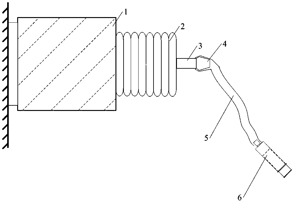
Various tests of oil samples have high requirements on the quality of the obtained oil samples, and a little air, impurities or moisture mixed in the oil taken on site are enough to affect the judgment of the test results, such as figure 1 As shown, the existing oil outlet joint of power transformer or reactor includes oil outlet main valve 1, oil outlet pipe 2 and oil outlet head 3, and oil outlet head 3 is provided with oil outlet hole 4. Currently, the oil outlet personnel generally Rely on simple rubber tube 5, wrench, syringe 6 and other tools to take oil, disassemble and assemble parts through wrench, and finally connect the rubber tube to the outside of the oil outlet hole 4, and the syringe 6 is connected to the oil outlet end of the rubber tube 5, so that Carrying out the oil extraction operation, the above-mentioned whole process, for unskilled personnel, it is very likely that the air, impurities or moisture mixed in the oil sample of the syringe 6 will pollute the oil sample during the oil extraction, and the transformer or reactor The oil outlet hole 4 is exposed to the air, and it is inevitable to be polluted by impurities such as water and dust during the oil outlet process, and the oil flow may splash around, causing the embarrassing situation that the working environment is dirty and busy

Method used


Image

  • Oil extraction transition joint for transformer or reactor
  • Oil extraction transition joint for transformer or reactor

Examples


Embodiment Construction

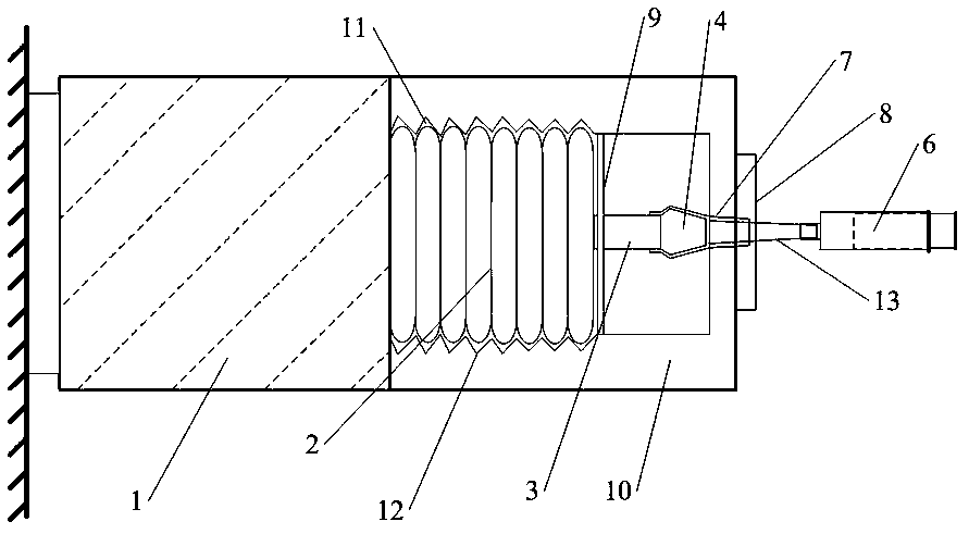
[0016] Such as figure 1 with 2 As shown, the present invention includes an oil extraction joint, and the oil extraction joint includes an oil outlet main valve 1, an oil extraction pipe 2 and an oil outlet head 3, and also includes a transition joint, and the transition joint is sleeved on the oil extraction port. On the joint; the transition joint includes a hollow cylindrical structure joint body 10 and a transition rubber sleeve 7 and a hard thin tube 13 arranged in the hollow cylindrical structure joint body 10, and the hollow cylindrical structure joint body 10 A connecting chamber 11 is provided on one side of the connecting chamber 11, and a joint engaging thread 12 is arranged on the inner wall of the connecting chamber 11; a reverse engaging thread is arranged on the outside of the oil taking pipe 2, and the reverse engaging thread and the connecting chamber The joint on the inner wall of 11 is matched with the thread 12; the inner end of the connection chamber 11 is...


PUM


Abstract

The invention discloses an oil extraction transition joint for a transformer or a reactor. The oil extraction transition joint comprises an oil extraction joint body. The oil extraction joint body comprises an oil outlet hole main valve, an oil extraction pipe and an oil outlet head and further comprises a transition joint body. The oil extraction joint body is sleeved with the transition joint body. The transition joint body comprises a hollow cylinder structure joint body, a transition rubber sleeve and a hard thin tube, wherein the transition rubber sleeve and the hard thin tube are arranged in the hollow cylinder structure joint body. According to the oil extraction transition joint, after the transition joint of the transformer or the reactor is unscrewed, the transition joint body isin butt joint with the original position of the oil extraction joint body, the oil extraction pipe is hermetically connected through the coating of a connection cavity, and the oil outlet head is hermetically coated through the transition rubber sleeve, so that oil outlet holes can produce oil in a sealed state, zero pollution of an oil sample can be realized, the working process is neat and orderly, the use is flexible and convenient, and the working efficiency is greatly improved.

Description

technical field [0001] The invention relates to the technical field of transformers or reactor tools, in particular to an oil-taking transition joint for transformers or reactors. Background technique [0002] At present, the quality of the insulating oil of a power transformer or reactor can reflect the insulation state of the transformer or reactor. When a transformer or reactor fails, it can be reflected by various tests such as oil chromatography and gas content of the insulating oil The nature and causes of defects inside transformers or reactors, etc. Therefore, substation operation and maintenance personnel need to regularly take insulating oil samples for transformers or reactors according to the plan. Various tests of oil samples have high requirements on the quality of the obtained oil samples, and a little air, impurities or moisture mixed in the oil taken on site are enough to affect the judgment of the test results, such as figure 1 As shown, the existing oil o...

Claims


Application Information

Patent Timeline
Patent Type & Authority Applications(China)
IPC IPC(8): F16L15/04G01N1/10
CPCF16L15/04G01N1/10G01N2001/1031
Inventor 郭磊张劲光王栋张科董曼玲丁国君董丽洁周少珍
Owner STATE GRID HENAN ELECTRIC POWER ELECTRIC POWER SCI RES INST
Learn More