Dry ice cleaning device and cleaning method thereof

A technology of dry ice cleaning and dry ice, which is applied in the field of cleaning and food hygiene, to achieve good cleaning effect, fast spraying speed and increased kinetic energy

Inactive Publication Date: 2012-01-25
EAST CHINA UNIV OF SCI & TECH
View PDF7 Cites 18 Cited by
  • Summary
  • Abstract
  • Description
  • Claims
  • Application Information

AI Technical Summary

Problems solved by technology

[0005] However, most of the dry ice blasting technology is still used in industrial c

Method used


Image

  • Dry ice cleaning device and cleaning method thereof
  • Dry ice cleaning device and cleaning method thereof
  • Dry ice cleaning device and cleaning method thereof

Examples


Embodiment 1

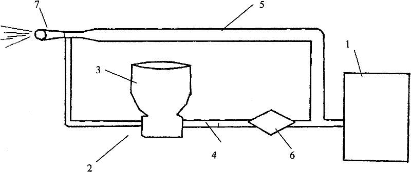
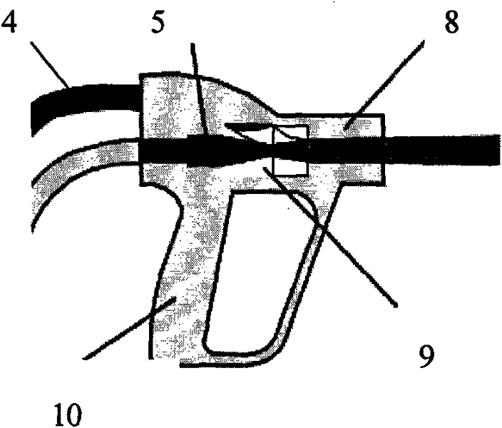
[0063] Such as figure 1 As shown, the dry ice blasting device of the present invention is a dishwasher, including an air compression system and an injection system connected thereto. A pipeline and a low-pressure gas pipeline. The low-pressure gas pipeline is provided with a material distribution mechanism and a pressure reducing valve. The high-pressure gas pipeline adopts a Venturi nozzle, and the air compression system communicates with the nozzle through the Venturi nozzle.

[0064] The outlet end of the material distributing mechanism communicates with the end of the Venturi nozzle of the air compression system and connects with the injection system. The diameter of the Venturi nozzle is 3-5mm.

[0065] The material distribution mechanism includes a dry ice material cylinder and a material distributor. The bottom of the cylindrical dry ice material cylinder in the material distribution mechanism is equipped with a material distributor, and is connected with a low-pressu...

Embodiment 2

[0077] Except for the following differences, it is the same as in Example 1, and a dry ice blasting device is prepared for dry ice blasting. The diameter of the Venturi nozzle is 4-6mm, and the pressure of the air compressor is 0.6MPa. The pressure of the high-pressure pipeline is set at 0.6MPa, and the pressure of the low-pressure pipeline is set at 0.16MPa. The Mach value of the jetting speed of the dry ice particles is 2.3-2.6, and the jetting amount of the dry ice particles from the nozzle is 38-40g per minute.

Embodiment 3

[0079] Except for the following differences, it is the same as in Example 1, and a dry ice blasting device is prepared for dry ice blasting.

[0080] The diameter of the Venturi nozzle is 7 mm, and the pressure of the air compressor is 0.7 MPa. The pressure of the high-pressure pipeline is set at 0.65MPa, and the pressure of the low-pressure pipeline is set at 0.20MPa. The Mach value of the jetting speed of the dry ice particles is 2.0-2.2, and the jetting amount of the dry ice particles from the nozzle is between 40-45g per minute.


PUM


Abstract

The invention provides a dry ice cleaning device and a cleaning method thereof. The device comprises an air compressed system and an injection system communicated with the air compressed system, wherein the air compressed system comprises an air compressor, a high-pressure gas pipeline and a low-pressure gas pipeline; the high-pressure gas pipeline and the low-pressure gas pipeline are respectively communicated with the air compressor and converge to the injection system through independently moving; a material division mechanism and a reducing valve are arranged on the low-pressure gas pipeline; the high-pressure gas pipeline adopts a venturi spray pipe; the air compressed system is communicated with a nozzle through the venturi spray pipe; and the outlet end of the material division mechanism is communicated with the tail end of the venturi spray pipe in the air compressed system and is connected with the injection system. According to the invention, water resources can be saved, the operating cost is reduced, and simultaneously, no cleaning agent residues exist; the exhaust gas of carbon dioxide is utilized, so that the emission of greenhouse gases is reduced; and the surface of a cleaned object cannot be damaged, and a low-temperature disinfection function is achieved. At the same time, in the invention, the dry ice cleaning device for industrial use is miniaturized so as to be applied to the field of family food sanitation.

Description

technical field [0001] The invention relates to the field of cleaning technology, in particular to a dry ice cleaning device using dry ice as a cleaning medium and a cleaning method thereof. The dry ice cleaning device and cleaning method thereof are particularly suitable for the field of food hygiene. Background technique [0002] Dry ice is solid carbon dioxide, CO 2 It is one of the main application products in social production, but people are concerned about CO 2 applications are very limited. At present, countries around the world are seeking effective methods and measures to reduce the harm to the human living environment, and people are also actively exploring how to use CO 2 The characteristics are applied in industrial and civil ways. [0003] At present, traditional physical and chemical cleaning methods are still mainly used in the cleaning industry in our country. Because traditional physical cleaning methods often damage the surface of the cleaned object, c...

Claims


Application Information

Patent Timeline
IPC IPC(8): B08B7/00
Inventor 惠虎张剑睿匡以武王刚王永佳
Owner EAST CHINA UNIV OF SCI & TECH
Why Eureka
Try Eureka