

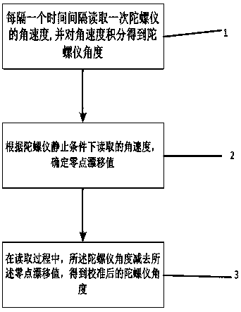
Calibration method of gyroscope zero drift
A calibration method and zero-point drift technology, applied in instruments, measuring devices, etc., can solve the problems of affecting sensor accuracy, unrealistic processing speed, poor user experience, etc., and achieve the effect of low cost, less calculation, and fast response
- Summary
- Abstract
- Description
- Claims
- Application Information
AI Technical Summary
Problems solved by technology
Method used
Image

Examples
Embodiment Construction
[0026] The technical solutions in the embodiments of the present invention will be described in detail below with reference to the drawings in the embodiments of the present invention. It should be understood that the specific embodiments described below are only used to explain the present invention, not to limit the present invention.
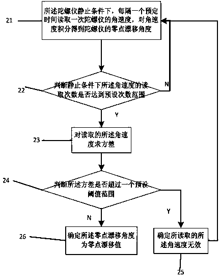
[0027] The calibration method in this embodiment can be implemented according to different calibration strategies, specifically, periodic calibration is performed according to a preset period, and real-time calibration can also be performed. In the specific implementation, if the calibration is performed according to the preset cycle, the calibration cycle needs to be set in advance, such as half an hour, one hour, twelve hours, etc., that is, the robot will actively stop every interval of the preset cycle. Perform a monitoring to complete the calibration. Of course, the preset cycle can also be dynamically changed, and the specific cycle le...
PUM
 Abstract
Description
Claims
Application Information