
Amplitude control based aviation engine blade vibration fatigue testing method

A technology for engine blades and aero-engines, which is applied in vibration testing, machine/structural component testing, and measuring devices. It can solve the problems of reducing the reliability of blade vibration fatigue test results, and the fluctuation cannot be kept stable, so as to eliminate amplitude fluctuations and The effect of excessive life error

Inactive Publication Date: 2018-06-22
SOUTHEAST UNIV
View PDF6 Cites 17 Cited by
  • Summary
  • Abstract
  • Description
  • Claims
  • Application Information

AI Technical Summary

Problems solved by technology

Since the vibrating table uses the acceleration control mode, in the vibration fatigue process, in order to keep the acceleration constant, the driving voltage of the vibrating table will be slightly adjusted, and the blades of the aero-engine are made of low-damping alloy material, which presents a narrow and high amplitude when resonating. The frequency response characteristics, under the action of resonance amplification, cause huge fluctuations in the amplitude of the blade, making the amplitude (strain) fluctuation range of the blade exceed 10% or even higher of the predetermined amplitude, and the fluctuation is too large to maintain stability, thereby reducing the blade Reliability of Vibration Fatigue Test Results

Method used


Image

  • Amplitude control based aviation engine blade vibration fatigue testing method
  • Amplitude control based aviation engine blade vibration fatigue testing method
  • Amplitude control based aviation engine blade vibration fatigue testing method

Examples


Embodiment Construction

[0019] Below in conjunction with accompanying drawing, technical scheme of the present invention is described in further detail:

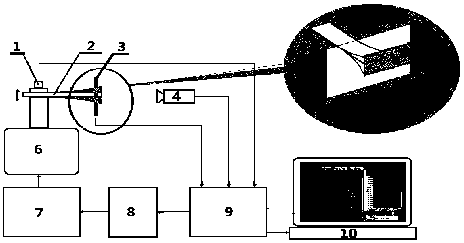
[0020] In order to make the test possible, the present invention firstly provides a vibration fatigue test device for aero-engine blades based on amplitude control. The displacement response at one end is obtained by non-contact laser displacement sensors 3 and 5, wherein the non-contact laser displacement sensors 3 and 5 are placed perpendicular to the engine blade 2, and a digital optical vibration amplitude calibration module 4 is provided on the outside of the blade to assist in calibrating the non-contact The blade end displacement response obtained by the laser displacement sensor, the non-contact laser displacement sensor 3,5, the digital optical vibration amplitude calibration module 4 are connected to the computer 9, and the computer 9 is connected to the display 10, the programmable vibration control module 8, the power An amplifier 7, th...


PUM


Abstract

The invention discloses an amplitude control based aviation engine blade vibration fatigue testing method. A non-contact laser amplitude monitoring system is adopted. The amplitude of the end parts ofblades of an engine is monitored in real time. The amplitude of the end parts of the blades of the engine is taken as feedback signals. If that the dynamic amplitude deviates from a test preset valueis detected, a measurement and control system sends a modification command in real time. The amplitude constancy of the end parts of the blades of the engine is maintained through adjusting the magnitude of excitation drive current or adjusting excitation frequency. The amplitude control precision is superior to 1%. Therefore, a reliable blade vibration fatigue testing result can be acquired.

Description

technical field [0001] The invention belongs to the technical field of vibration fatigue tests, in particular to an aeroengine blade vibration fatigue test method based on amplitude control. Background technique [0002] The fatigue failure caused by the vibration of the blade is the main failure mode of the compressor blade under the action of the periodic airflow excitation force of the aero-engine compressor. The failure of blades will directly affect the stability of the engine, and even cause catastrophic aviation accidents. Therefore, it is of great significance to study the vibration fatigue life of engine blades to ensure the normal and stable operation of the engine. [0003] In the traditional blade vibration fatigue test, the blade is usually rigidly fixed on the surface of the electromagnetic vibrating table, and the excitation frequency is selected near the first-order resonance frequency of the blade by using the principle of resonance amplification, and the b...

Claims


Application Information

Patent Timeline
Patent Type & Authority Applications(China)
IPC IPC(8): G01M7/02
CPCG01M7/022
Inventor 费庆国郑成林何顶顶黄跃平
Owner SOUTHEAST UNIV
Learn More