Eureka AIR delivers breakthrough ideas for toughest innovation challenges, trusted by R&D personnel around the world.

Phase defect detection system and method based on short-phase dry-dynamic Twyman interferometer

A defect detection and interferometer technology, used in instruments, measuring devices, scientific instruments, etc., can solve the problems of inability to resist environmental disturbances, too strict distance requirements, and sparse distribution, achieve low environmental requirements, achieve dynamic measurement, high The effect of resolution detection

Inactive Publication Date: 2018-06-22
NANJING UNIV OF SCI & TECH
View PDF6 Cites 18 Cited by
  • Summary
  • Abstract
  • Description
  • Claims
  • Application Information

AI Technical Summary

Problems solved by technology

Among them, PSDI is a point diffraction interferometer with a double-fiber structure proposed by Johnson. The disadvantage of this structure is that the distance between the two fibers is too strict. To ensure that the frequency of the linear carrier frequency stripes cannot exceed the sampling frequency of the CCD
This method has a simple structure and will not introduce defect interference from other components, but there are still some problems: 1) The distribution of defects is required to be sparse, and the distance between adjacent defects should not exceed 12mm; 2) The field of view is small, and only one time can be measured A phase defect in the field; 3) Mirrorless imaging technology is required to map the amplitude and phase distribution of the CCD target surface to the sample surface, and the calculation is complicated; 4) Cannot resist environmental disturbances

Method used


Image

  • Phase defect detection system and method based on short-phase dry-dynamic Twyman interferometer
  • Phase defect detection system and method based on short-phase dry-dynamic Twyman interferometer

Examples


Embodiment 1

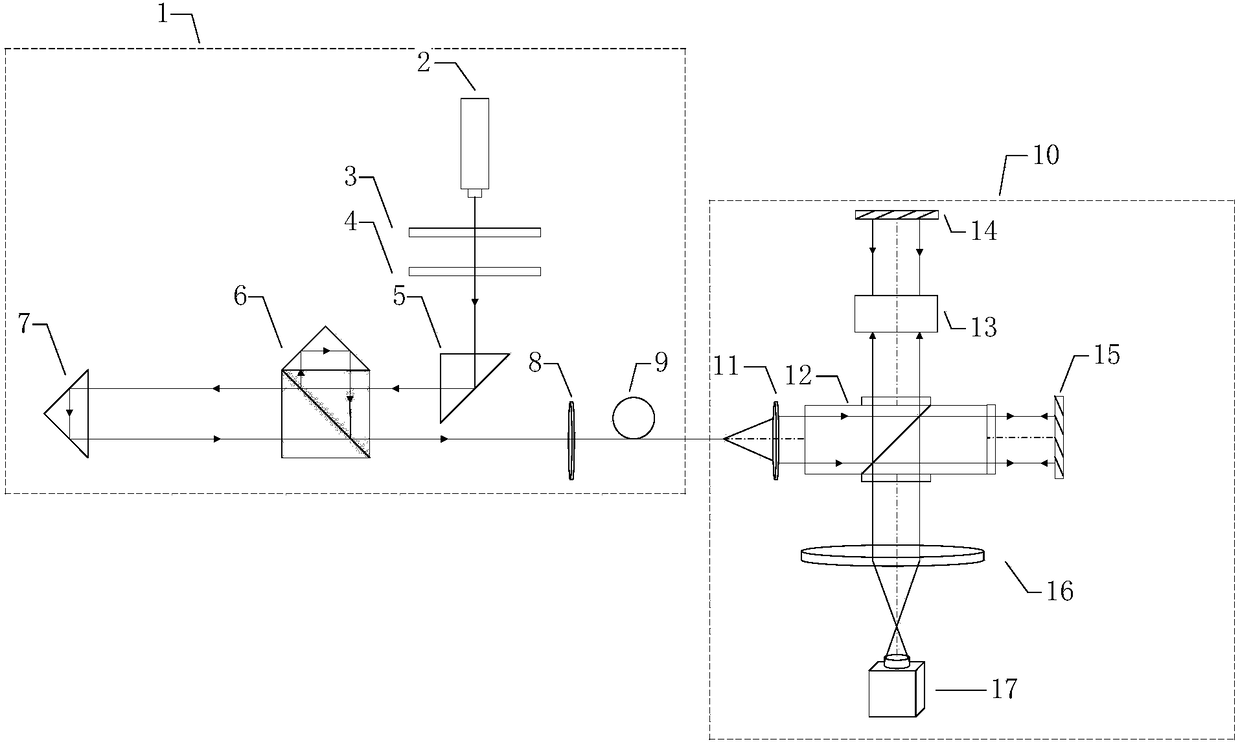
[0030] The optical path structure of the phase defect detection system based on the short coherent dynamic Tyman interferometer of the present invention is as follows: figure 1 shown, including:

[0031] 1) The short coherent polarized light source 1 is used to generate a pair of linearly polarized lights with phase retardation and orthogonal polarization directions. The short coherent polarized light source 1 includes a short coherent laser 2 , a polarizer 3 , a half-wave plate 4 , a first pyramid 5 , a PBS pyramid glued 6 , a second pyramid 7 , and a coupling lens 8 , which are sequentially arranged on a common optical axis. and the polarization-maintaining fiber 9; the polarizer 3 and the half-wave plate 4 jointly generate polarized light, the PBS corner cone glue 6 reflects s ​​light, and transmits p light, and the distance between the second corner cone 7 and the PBS corner cone glue 6 is Δ , the optical path difference between s light and p light is 2Δ and the polarizat...


PUM


Abstract

The invention discloses a phase defect detection system and method based on a short-phase dry-dynamic Twyman interferometer. The system comprises two parts including a short-phase dry polarization light source and a polarization Twyman interferometer. The method comprises the following steps: firstly, enabling a light beam emitted by a short-phase laser device to pass through a polaroid and a half-wave plate and enter a Michelson interference structure; emitting a pair of linearly polarized light with orthogonal polarization directions and coupling the pair of linearly polarized light into a polarization-maintaining optical fiber; taking the linearly polarized light as a light source of a main interferometer; then adjusting a PZT (Piezoelectric Transducer) to be matched with phase difference of an interference cavity of an interferometer main body part; compensating phase delay between reference light and testing light; finally, acquiring four interference figures with the phase shifting amount difference of pi / 2 in sequence by utilizing a polarization camera; solving through a phase-shifting algorithm to obtain information of phase defects. The phase defect detection system and method, disclosed by the invention, have the advantages of large view field, high resolution ratio, good shock resistance and simplicity in operation and can be used for real-time and high-precision detection of the phase defects of an optical element.

Description

technical field [0001] The invention belongs to the technical field of optical interferometric measuring instruments, in particular to a phase defect detection system and method based on a short-coherence dynamic Taiman interferometer. Background technique [0002] The defects of optical components can be divided into amplitude defects and phase defects. During application, amplitude defects in optical components can cause energy scattering, while phase defects can cause the energy of the transmitted beam of the optical system to converge, thereby destroying optical components or coatings. Especially in high-power laser systems, phase defects on optical components are the main cause of laser damage. [0003] In recent years, the measurement of nano-scale defects has attracted more and more attention, so the demand for precision measurement instruments with high resolution and large field of view is increasing. The Line Scanning Phase Differential Imaging (LPDI) proposed by...

Claims


Application Information

Patent Timeline
IPC IPC(8): G01N21/958
CPCG01N21/958
Inventor 陈磊马云李建欣朱文华刘一鸣刘致远丁煜杨影
Owner NANJING UNIV OF SCI & TECH
Why Eureka
Eureka Blog
Learn More