Subsynchronous oscillation suppressing method and device for wind generation set
A subsynchronous oscillation, wind turbine technology, applied in circuit devices, wind power generation, reducing/preventing power oscillation, etc., to achieve the effect of easy engineering transformation, no hardware circuit transformation cost, and suppression of subsynchronous oscillation
- Summary
- Abstract
- Description
- Claims
- Application Information
AI Technical Summary
Problems solved by technology
Method used
Image

Examples
Embodiment Construction
[0044] The following will clearly and completely describe the technical solutions in the embodiments of the present invention with reference to the accompanying drawings in the embodiments of the present invention. Obviously, the described embodiments are only some, not all, embodiments of the present invention. Based on the embodiments of the present invention, all other embodiments obtained by those skilled in the art without creative efforts fall within the protection scope of the present invention.
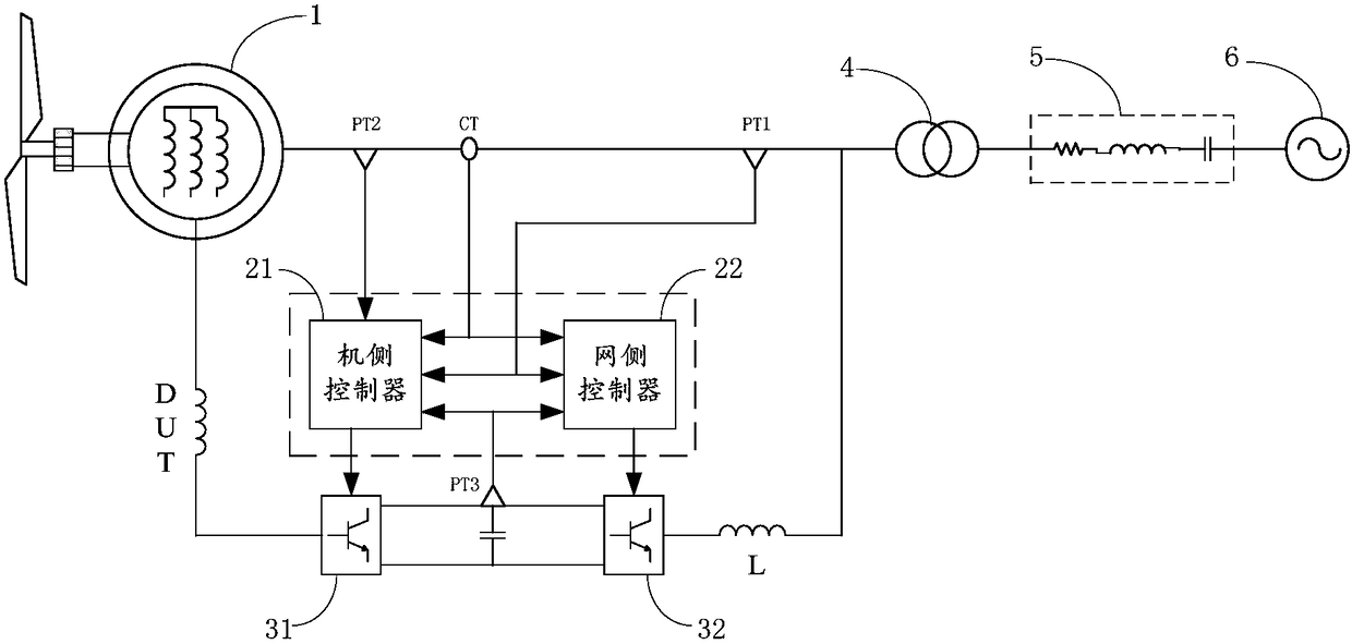
[0045] figure 1 It is the connection schematic diagram of the wind turbine connected to the grid through the series compensation line, as shown in figure 1 As shown, the converter controller controls the converter, and transmits the electric energy generated by the doubly-fed induction generator 1 to the power grid 6 through the transformer 4 and the series compensation line 5, wherein the converter controller includes a machine-side controller 21 and The grid-side controller...
PUM
 Abstract
Description
Claims
Application Information