Automatic power-on and power-off router

A router, power-on and power-off technology, applied in electrical components, electrical equipment structural parts, cooling/ventilation/heating renovation, etc., can solve the problems of automatic power-off of routers, power waste, etc., to reduce space occupancy and life. Cost, power saving effect

Inactive Publication Date: 2018-06-22
ZHENGZHOU QISHUO ELECTRONICS TECH CO LTD
View PDF0 Cites 0 Cited by
  • Summary
  • Abstract
  • Description
  • Claims
  • Application Information

AI Technical Summary

Problems solved by technology

[0005] The purpose of the present invention is: in order to solve the problem that the existing router cannot automatically cut off the power when the household goes out, resulting in the waste of electric energy, the present invention provides a router that can automatically turn on and off the power, and the high and low power generated by the common emitter amplifier circuit The flat input relay control circuit controls the on and off of the relay, and then controls the automatic power on and off of the router to achieve the purpose of saving electric energy. It has the advantages of energy saving, emission reduction and simple structure.

Method used


Image

  • Automatic power-on and power-off router
  • Automatic power-on and power-off router
  • Automatic power-on and power-off router

Examples


Embodiment 1

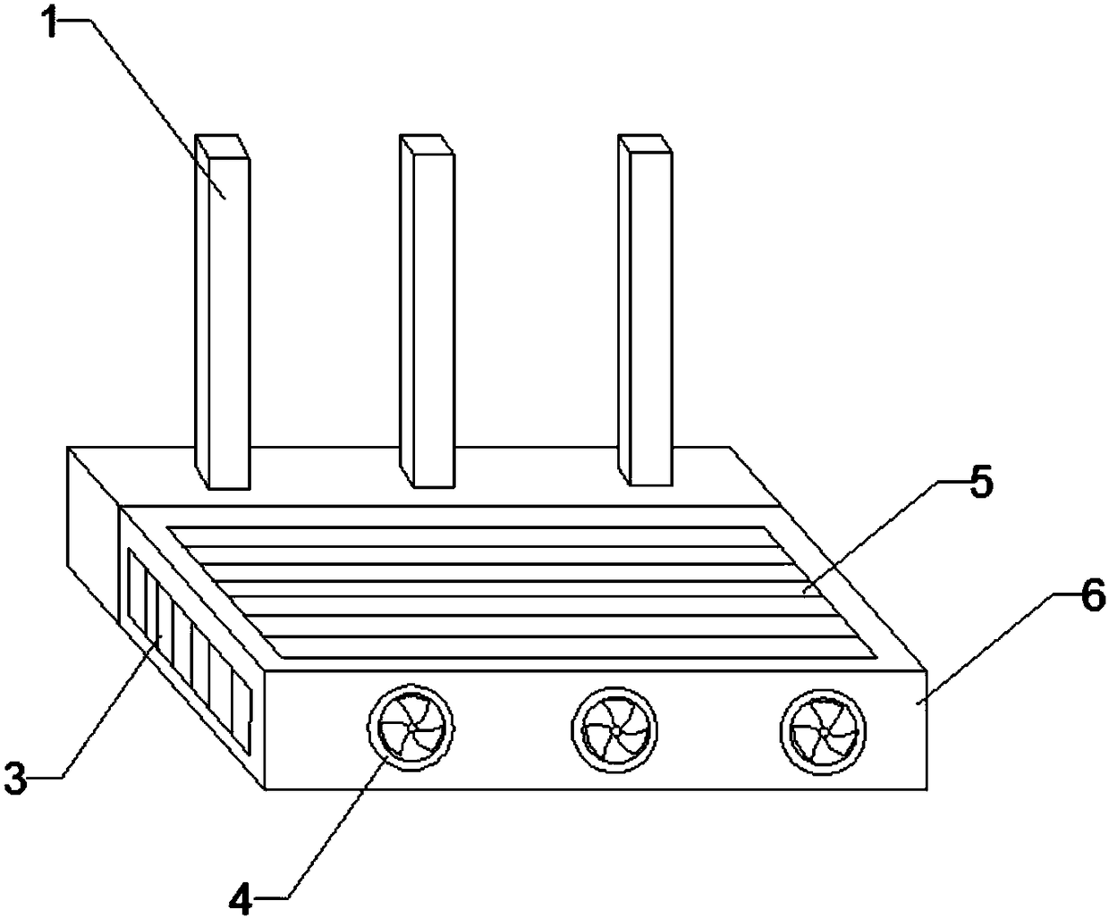
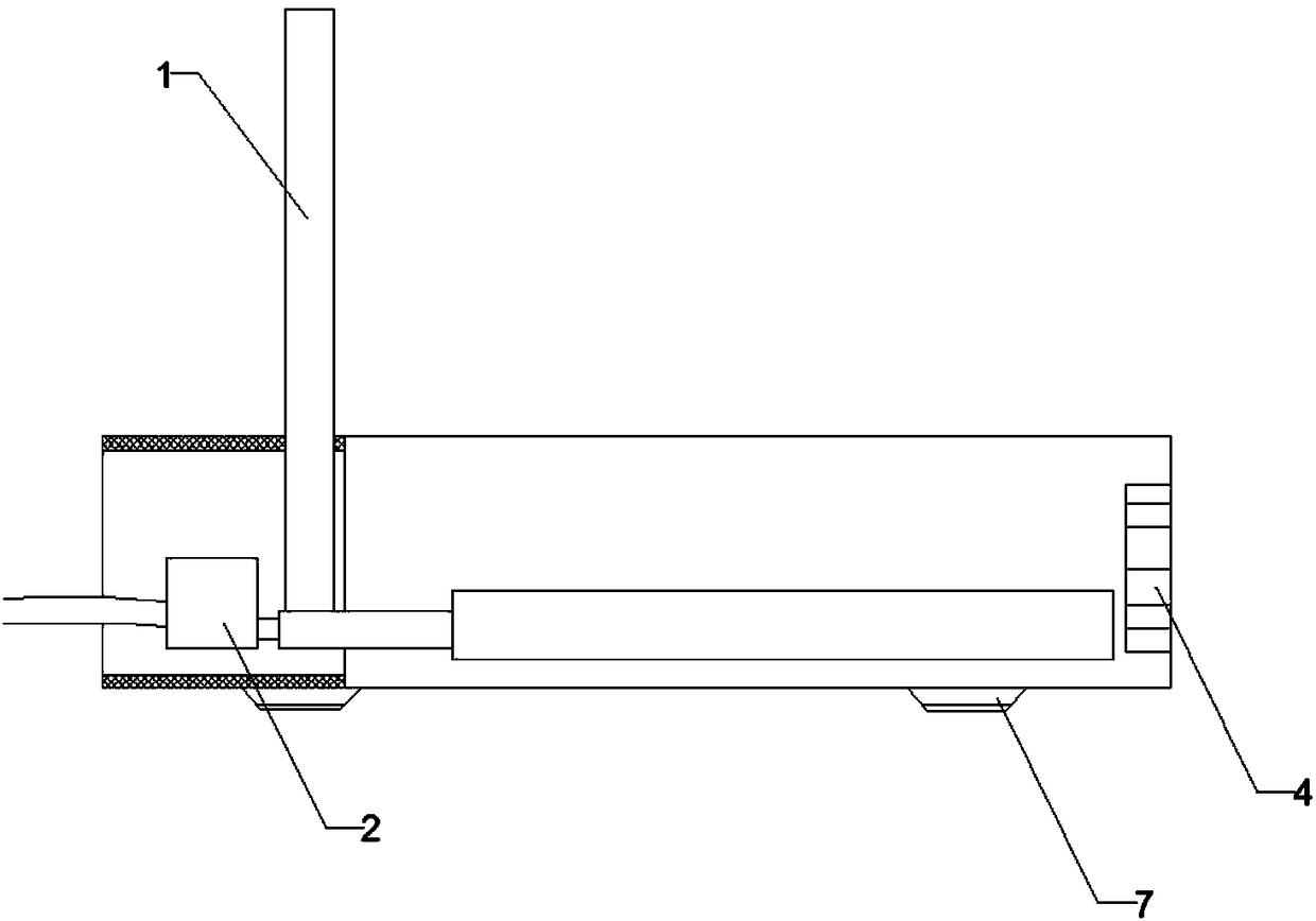
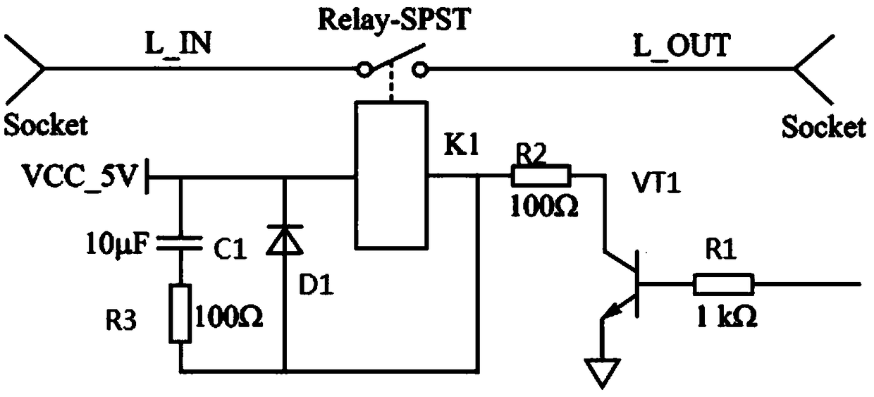
[0025] Such as figure 1 As shown, a router with automatic power on and off includes a casing main body 6 and an antenna 1. The casing main body 6 is provided with a switch control circuit 2, and the switch control circuit 2 includes a resistor R1, a resistor R2, and a resistor R3. , capacitor C1, diode D1, transistor VT1, relay K1 and the single-pole single-throw switch SPST controlled by relay K1, one end of the resistor R1 is connected to the base of the transistor VT1, the emitter of the transistor VT1 is grounded, and the collector is connected to the One end of the resistor R2 is connected, and the other end of the resistor R2 is connected with three parallel branches. The branch 1 is provided with a relay K1, and the branch 2 is provided with a diode D1. The cathode of the diode D1 is connected to a 5V power supply. 3 is provided with a capacitor C1 and a resistor R3 connected in series, the capacitor C1 is connected to a 5V power supply, and the two ends of the single-p...

Embodiment 2

[0031] On the basis of Embodiment 1, this embodiment is also provided with a fan 4, a side heat dissipation window 3, and a top heat dissipation window 5 on the casing main body 6, and the side heat dissipation window 3 is arranged on the router casing On both sides of the main body 6 , the top heat dissipation windows 5 are arranged above the casing main body 6 , and the fan ( 4 ) is arranged in front of the casing main body 6 .

[0032] As a preferred embodiment, the side heat dissipation windows 3 and the top heat dissipation windows 5 are louver structures, which can block the entry of most dust while ensuring heat dissipation.

[0033] As a preferred embodiment, the fan 4 is provided with three rotating blades, and the air outlet of the fan 4 faces the inside of the main body of the casing, which can effectively reduce the temperature inside the router and discharge the internal dust at the same time. The material of the fan 4 blades is Made of plastic material, the overa...


PUM


Abstract

The invention discloses an automatic power-on and power-off router, and relates to the field of routers, in particular to an automatic power-on and power-off router for solving the problem that the router cannot achieve automatic power-off in the case of outgoing of a user, resulting in electric energy waste and increasing the power consumption of the user in the prior art. The automatic power-onand power-off router comprises a casing main body and an antenna, a switch control circuit is arranged in the casing main body, the switch control circuit comprises a resistor R1, a resistor R2, a resistor R3, a capacitor C1, a diode D1, a triode VT1, a relay K1 and a single-pole single-throw switch SPST controlled by the relay K1, one end of the R1 is externally connected with a high-low level input, the other end thereof is connected with the triode VT1, the turn-off of the triode VT1 is controlled by controlling the high-low level so as to control the turn-on and turn-off of the single-polesingle-throw switch corresponding to the relay K1, the power-on and power-off of the circuit are achieved, and the automatic power-on and power-off router has the advantages of simple structure, convenient operation, automatic energy saving and self-heat dissipation.

Description

technical field [0001] The invention relates to the field of routers, in particular to a router with automatic power on and off. Background technique [0002] A router is a device connected to various LANs and WANs in the Internet. It will automatically select and set routes according to the channel conditions, and send signals in the order of the best path. A router is also called a gateway device, which is used to connect multiple logic The so-called logical network represents a separate network or a subnet. When data is transmitted from one subnet to another, it can be completed by the routing function of the router. Therefore, the router has the ability to judge the network address and select the IP address. The function of the path, it can establish a flexible connection in a multi-network interconnection environment, and can connect various subnets with completely different data packets and media access methods. The router only accepts information from the source stati...

Claims


Application Information

Patent Timeline
Patent Type & Authority Applications(China)
IPC IPC(8): H04L12/771H04L12/12H05K7/20H04L45/60
CPCH04L12/12H04L45/60H05K7/20136
Inventor 高翔
Owner ZHENGZHOU QISHUO ELECTRONICS TECH CO LTD
Why Eureka
Try Eureka