Automatic power source PCB assembling machine and assembling mechanical arm thereof

A technology of PCB board and automation group, which is applied in the field of power supply PCB board automatic assembly machine and its assembly manipulator, can solve the problems of high cost, low efficiency of manual board insertion and fastening, and difficulty in ensuring the consistency of assembled products.

Pending Publication Date: 2018-06-26
SHENZHEN XING GRAIN AUTOMATION CO LTD
View PDF0 Cites 16 Cited by
  • Summary
  • Abstract
  • Description
  • Claims
  • Application Information

AI Technical Summary

Problems solved by technology

In traditional power assembly, the insertion of the PCB board and the fastening of the DC line connector are generally completed manually. The manual insertion and fastening of the board is inefficient, and it is difficult to ensure the consistency of the assembled product; The cost of manual assembly of power PCB boards and DC line connectors is getting higher and higher; automatic assembly of power supply PCB boards and DC line connectors is a future development trend; however, there are the following technical difficulties in the design of automatic assembly of power supply PCB boards and DC line connectors : 1. Since the PCB board and the DC line connector need to be welded and fixed to each other before assembly, the upper cover needs to be closed on the lower cover after the assembly is completed, so a set of jigs that can assist in completing the above process at the same time is required; 2. During assembly The lower cover needs to be fixed, and the PCB board is placed horizontally when the PCB board is connected to the DC line connector before assembly, so the horizontally placed PCB board needs to be inserted vertically into the lower cover during assembly; 3. The DC line connector is installed horizontally before assembly One side of the PCB board and connected to the PCB board, so when the PCB board is assembled, the DC line connector needs to be assembled synchronously, and the DC line connector needs to be rotated so that it can be embedded in the slot of the lower cover

Method used


Image

  • Automatic power source PCB assembling machine and assembling mechanical arm thereof
  • Automatic power source PCB assembling machine and assembling mechanical arm thereof
  • Automatic power source PCB assembling machine and assembling mechanical arm thereof

Examples


Embodiment Construction

[0025] The present invention will be further described below in conjunction with accompanying drawing:

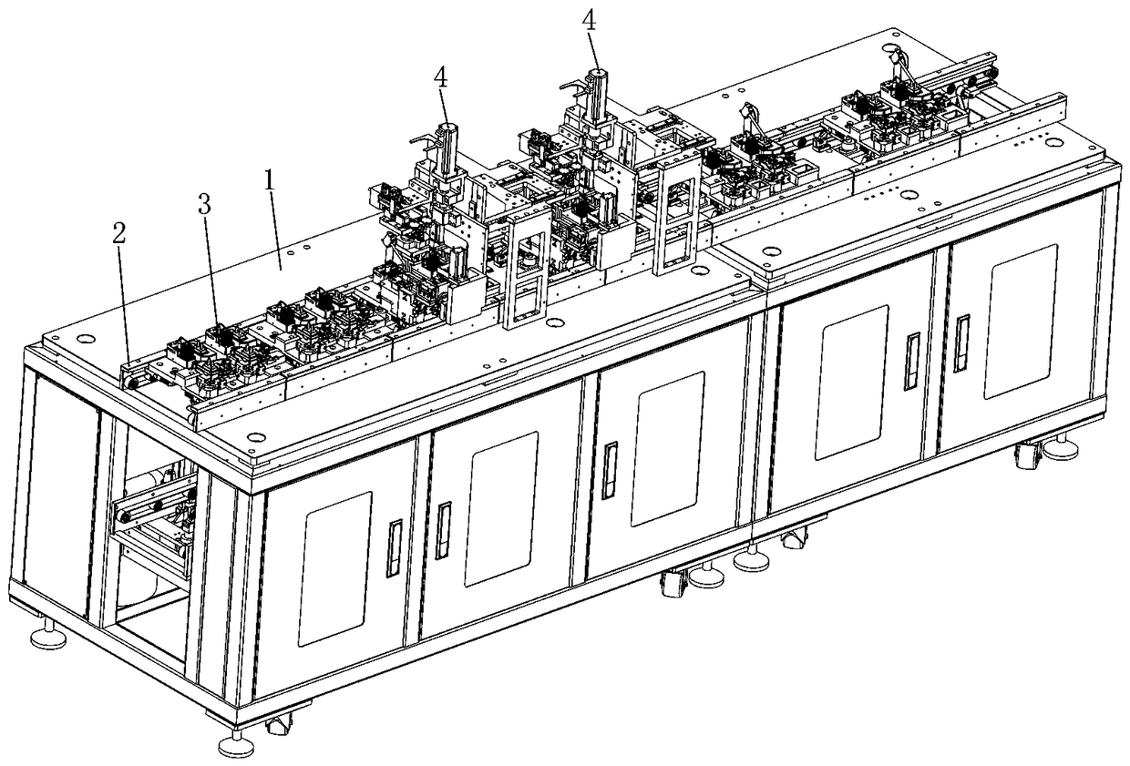
[0026] like Figure 1 to Figure 6 As shown, the technical solution adopted by the present invention is as follows: a power supply PCB board automatic assembly machine, including a transmission puller 2, a jig 3 and a gusset wire insertion manipulator 4, wherein the above-mentioned transmission puller 2 is arranged on the machine along a straight line. On the frame 1, a linear feeding space is formed in the middle of the transmission pull body 2, and at least two pinch plate insertion stations are arranged on the linear feeding space; the above-mentioned jig 3 includes at least two, and the jig 3 is placed on the transmission pull body 2 , and is supported by the synchronous belts on the front and rear sides of the transmission pull body 2, the synchronous belt drives the jig 3 to move linearly along the linear feeding space to the pinch plate insertion station; the first su...


PUM


Abstract

The invention discloses an automatic power source PCB assembling machine and an assembling mechanical arm of the automatic power source PCB assembling machine. The automatic power source PCB assembling machine comprises a conveying pull body, at least two jigs and at least two buckle plate wire plugging mechanical arms. The conveying pull body is arranged on the machine frame in the linear direction. The jigs are arranged on the conveying pull body. A first support seat, a second support seat and a third support seat of each jig are provided with a lower cover, a PCB and a DC wire connector connected with the PCB correspondingly in an embedded manner. The arrangement direction of the DC wire connector is perpendicular to the long side edge of the PCB. The buckle plate wire plugging mechanical arms are arranged on the buckle plate wire plugging station. The automatic power source PCB assembling machine can assist in connecting the DC wire connector with the PCB, assembling the PCB, theCD wire and the lower cover, automatically and synchronously completing vertical insertion of the PCB and rotating and buckling the DC wire connector for assembly at the same time.

Description

technical field [0001] The invention relates to the field of mechanical automation, in particular to an automatic assembly machine for a power PCB board and an assembly manipulator thereof. Background technique [0002] The power supply (portable charger) is a very commonly used electronic accessory, which is used for power import of electronic products such as mobile phones and tablet computers; the power supply is assembled from PCB board, DC line connector, upper cover, lower cover and other components to realize The circuit is turned on. Among them, the circuit conduction of the power supply needs to weld the PCB board and the DC line. One end of the DC line is electrically connected to the wiring hole on the PCB board, and the other end is the power connector. The PCB board is connected to the electrical connection piece of the upper cover. The chip is inserted into the socket, and the power connector is inserted into the portable product to be used to realize power tr...

Claims


Application Information

Patent Timeline
IPC IPC(8): B23P21/00B23P19/00H05K13/04
CPCH05K13/04B23P19/001B23P21/00
Inventor 章胜华刘美权
Owner SHENZHEN XING GRAIN AUTOMATION CO LTD
Why Eureka
Try Eureka