Shock absorption device for highway bridge

A shock absorption device and technology for highway bridges, applied in the field of bridge shock absorption, can solve the problems of failure to meet the requirements of shock absorption, affecting the normal use of bridges, reducing shock absorption performance, etc., to achieve extended service life, good shock absorption effect, The effect of prolonging the life cycle

Inactive Publication Date: 2018-06-26
魏志峰 +10
View PDF7 Cites 5 Cited by
  • Summary
  • Abstract
  • Description
  • Claims
  • Application Information

AI Technical Summary

Problems solved by technology

A bridge is generally composed of a superstructure, a substructure, a support and ancillary structures. The superstructure is also called a bridge span structure, which is the main structure for crossing obstacles; the substructure includes abutments, piers and foundations; Or the force transmission device installed at the supporting place of the bridge abutment; the auxiliary structures refer to the bridge head plate, conical slope protection, bank protection, diversion engineering, etc. With the frequent occurrence of earthquake disasters in recent years, people pay more attention to the earthquake resistance of bridges The height is getting higher and higher, and the dependence on the aseismic performance of the bridge is getting stronger and stronger. The current bridge shock absorbing device can only perform shock absorption in the vertical direction, and cannot perform shock absorption in the horizontal direction, which cannot meet the requirements of shock absorption, and After the shock absorbing device is used for a period of time, the shock absorbing performance will gradually decrease, which will affect the normal use of the bridge

Method used


Image

  • Shock absorption device for highway bridge

Examples


Embodiment Construction

[0016] The following will clearly and completely describe the technical solutions in the embodiments of the present invention with reference to the accompanying drawings in the embodiments of the present invention. Obviously, the described embodiments are only some, not all, embodiments of the present invention. Based on the embodiments of the present invention, all other embodiments obtained by persons of ordinary skill in the art without making creative efforts belong to the protection scope of the present invention.

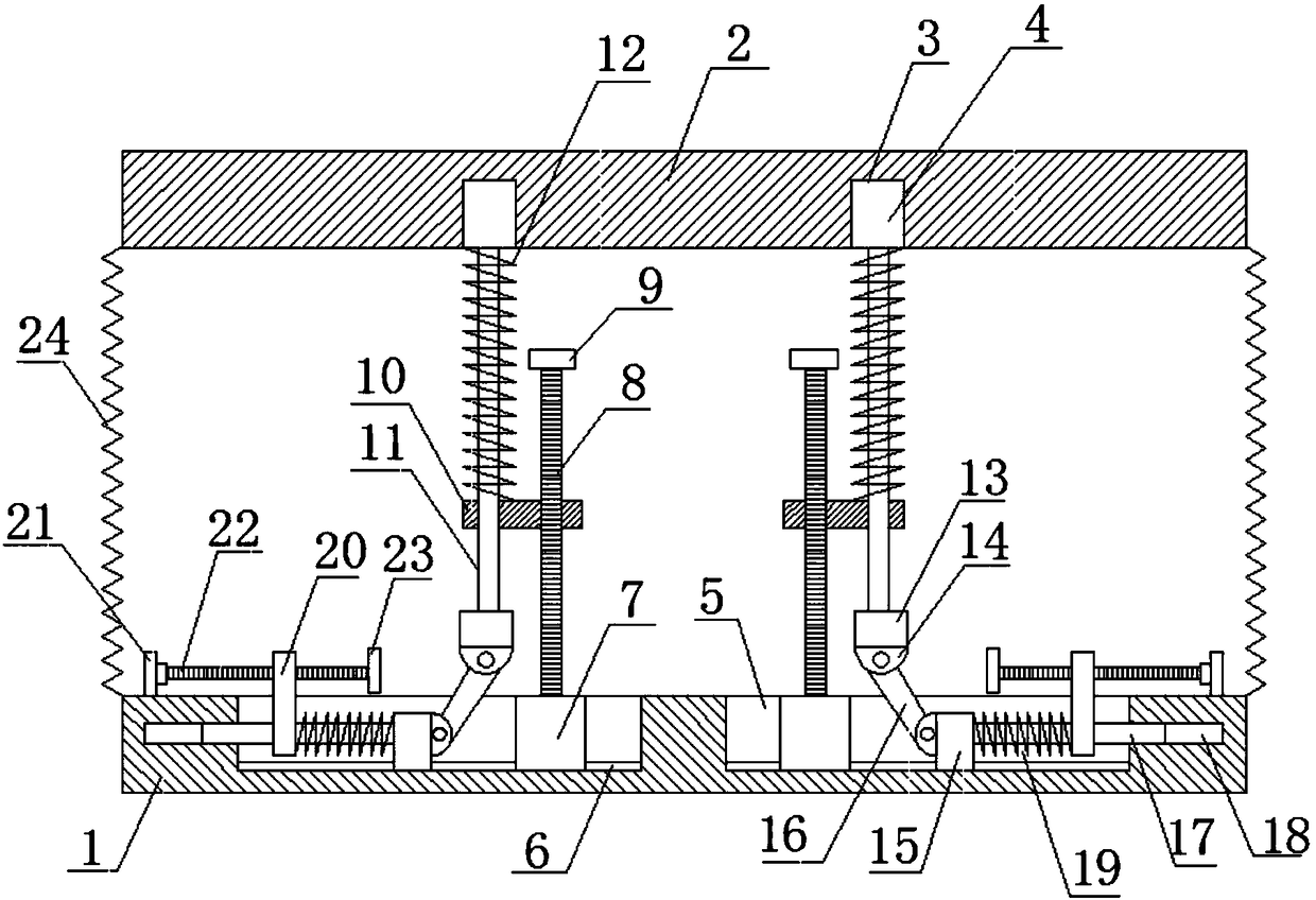
[0017] see figure 1 , in an embodiment of the present invention, a road bridge damping device includes a lower support 1 and an upper support 2, the lower side of the upper support 2 is symmetrically arranged with a fixed groove 3, and the fixed groove 3 A fixed block 4 is provided, the lower end of the fixed block 4 is provided with a first slide bar 11, the upper side of the lower support 1 is symmetrically provided with a groove 5, and the bottom of the gro...


PUM


Abstract

The invention discloses a shock absorption device for a highway bridge. The shock absorption device comprises a lower support and an upper support, wherein grooves are arranged at the upper side of the lower support in a bilaterally symmetrical manner; sliding rails are arranged at the bottom of the grooves; sliding blocks are arranged on the sliding rails; first threaded rods are arranged at theupper end of the sliding blocks; the first threaded rods are provided with first sliding plates; the lower parts of first sliding rods are slidably connected to the first sliding plates; each first shock absorption spring sleeved on the outside the corresponding first sliding rod is arranged between the corresponding first sliding plate and a corresponding fixing block; the sliding rails are alsoprovided with shock absorption seats; second sliding rods are arranged at the outside of the shock absorption seats; the lower parts of second sliding plates are slidably connected to the second sliding rods; each second sliding rod arranged between the corresponding second sliding plate and the corresponding shock absorption seat is sheathed with a corresponding second absorption spring; supportseats are arranged at the lower ends of the first sliding rods; connecting seats are arranged at the lower sides of the support seats; and the connecting seats are provided with connecting rods connected with the shock absorption seats. The shock absorption device for the highway bridge is simple in structure and easy to use, and is capable of not only horizontal shock absorption but also verticalshock absorption. The shock absorption effect is good and the service life of the shock absorption device is prolonged.

Description

technical field [0001] The invention relates to the technical field of bridge damping, in particular to a highway bridge damping device. Background technique [0002] Bridges generally refer to structures erected on rivers, lakes and seas to allow vehicles and pedestrians to pass smoothly. In order to adapt to the modern high-speed development of the transportation industry, bridges are also extended to buildings that cross mountain streams, poor geology or meet other transportation needs to make traffic more convenient. A bridge is generally composed of a superstructure, a substructure, a support and ancillary structures. The superstructure is also called a bridge span structure, which is the main structure for crossing obstacles; the substructure includes abutments, piers and foundations; Or the force transmission device installed at the supporting place of the bridge abutment; the auxiliary structures refer to the bridge head plate, conical slope protection, bank protect...

Claims


Application Information

Patent Timeline
Patent Type & Authority Applications(China)
IPC IPC(8): E01D19/04
CPCE01D19/041
Inventor 王晓瑜王振峰郝明瑞赵朝勋宋峰王现方田育民马红莉李文明牛丹洁魏志峰
Owner 魏志峰
Why Eureka
Try Eureka